Table of Contents
Advertisement
Advertisement
Table of Contents

Related Manuals for Radionics D7412G


Summary of Contents for Radionics D7412G
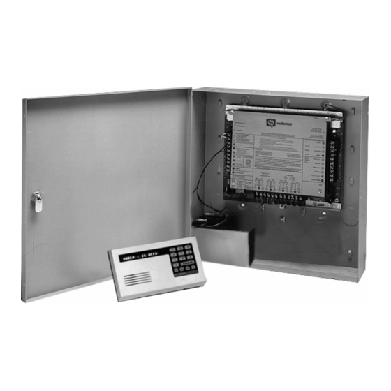
- Page 1 D9412G/D7412G Control/Communicators Operation and Installation Guide...
- Page 2 D9412G/D7412G Notes: D9412G/D7412G Operation & Installation Guide 43488D Page 2 © 2002 Radionics...
-
Page 3: Table Of Contents
Part 15 ............................11 1.4.2 Part 68 ............................11 Overview..................13 D9412G/D7412G Differences................13 Specifications ..................... 14 New Features in D9412G/D7412G ..............16 2.3.1 Introduction ........................... 16 2.3.2 Ground Fault Detect ........................16 2.3.3 Added Feature When Using Ground Fault Detect ..............16 2.3.4... - Page 4 Relay Installation .......................... 35 6.11.2 Phone Monitor Select Jumper ....................35 6.12 D928 Dual Phone Line Switcher ............... 35 6.12.1 Description ............................. 35 6.12.2 Operation ............................35 6.12.3 Watchdog Feature ........................36 D9412G/D7412G Operation & Installation Guide 43488D Page 4 © 2002 Radionics...
- Page 5 Point Parameters ....................37 Point Response Time ..................37 Wiring Information for Installations using the Ademco AB-12 Bell/Housing 38 Off-board Points ................39 Point (ZONEX) Bus D9412G Terminals D7412G Terminals ......................39 D8125, D8127 and D9127 POPIT Modules ............39 8.2.1...
- Page 6 D7412G Control/Communicator, 1 of 3 ............70 Appendix B: Point Address Charts ............... 71 ZONEX 1, Points 9 to 127 (D9412G); ZONEX 1, Points 9 to 75 (D7412G) ..71 ZONEX 2, Points 129 to 247 (D9412G Only) ............. 72 D9412G/D7412G Operation &...
- Page 7 Figure 12: On-board Point Sensor Loop Wiring ......................... 37 Figure 13: Wiring for Installations using the Ademco AB-12 Bell/Housing ................38 Figure 14a: Connecting the D8125 POPEX to the D9412G Panel ..................... 40 Figure 14b: Connecting the D8125 POPEX to the D7412G Panel ..................... 41 Figure 15: Program Record Sheet ...............................
- Page 8 D9412G/D7412G Contents Tables: Table 1: D9412G/D7412G Operation and Installation Guide Organization ................. 9 Table 2: Related Documentation ..............................10 Table 3: Differences Between the D9412G and D7412G ......................13 Table 4: Specifications ................................14 Table 5: Compatible Command Centers ............................. 17 Table 6: Listings ....................................
-
Page 9: Introduction
Throughout this manual, unless expressly stated, the words “panel” and “control/communicator” refer to both panels (D9412G and D7412G). Section 2.1 provides an overview of the differences between the D9412G and D7412G panels. Manual Organization This manual is divided into sections and appendices, summarized in the table below. -
Page 10: Related Documentation
Introduction Related Documentation Shown below is a comprehensive list of all documentation (with part numbers) directly related to the D9412G/ D7412G Control/Communicator panels. Throughout this manual, references are made to this documentation. If it is necessary to obtain one (or more) of these documents, please contact Radionics Technical Support and request the documentation by its corresponding part number. -
Page 11: Tips, Notes, Cautions And Warnings
User repairs must not be made, and doing so will void the user’s warranty. If the D9412G/D7412G Control/Communicators cause harm to the telephone network, the telephone company will attempt to notify you in advance. If advance notice isn’t practical, the telephone company will notify you as soon as possible. - Page 12 D9412G/D7412G Introduction Notes: D9412G/D7412G Operation & Installation Guide 43488D Page 12 © 2002 Radionics...
-
Page 13: Overview
D9131A Module connects to a parallel printer to print the event log. Figure 1: System Configuration D9412G/D7412G Differences The table below provides an overview of the differences between the D9412G and D7412G panels. New Features D9412G D7412G Access Control YES, 8 Doors... -
Page 14: Specifications
Ah) batteries using a D122. Current Requirements Panel : 500 mA alarm, 200 mA idle See Current Rating Chart for Standby Battery Calculations in the D9412G/D7412G Approved Applications Compliance Guide for the current draw requirements of other system components. Power Outputs All external connections are inherently power-limited except battery terminals. - Page 15 1.6 kΩ Compatible Enclosures D8103 Universal Enclosure, D8109 Fire Enclosure, D8108A Attack Resistant Enclosure Table 4 (cont’d): Specifications Compatible Accessories See the Radionics Product Catalog for a complete list. D122 Dual Battery Harness D1256 Fire Command Center D125B Powered Loop Interface Module...
-
Page 16: New Features In D9412G/D7412G
2.3.2 Ground Fault Detect In order for the D9412G/D7412G to be able to detect ground fault conditions, the Earth Ground Terminal on the control/communicators had to be electrically-isolated from all other terminals. A Ground Fault Detect Enable switch (S4) has been added to the panel and is located just under Terminal 10, Earth Ground. For more information on the operation of this function, see section 3.5.2 Ground Fault Detect Enable . -
Page 17: Command Centers
“request to exit” input, or from a command center. The access control features of the D9412G/D7412G can deny access during armed periods. It can also grant access only to certain authorized users depending on whether the area is master armed, perimeter armed, or disarmed. -
Page 18: Emi & Lightning Transient Protection
Their design significantly reduces electromagnetic interference and malfunction generally caused by lightning. 2.4.10 Programming Use either the Radionics D5200 Programmer or the Remote Account Manager (RAM IV) to program the D9412G/ D7412G Control/Communicators. Refer to the D9412G/D7412G Program Entry Guide for programming options. -
Page 19: Listings And Approvals
D9412G/D7412G Overview 2.4.14 Listings and Approvals The D9412G/D7412G Literature Pack includes the D9412G/D7412G Approved Applications Compliance Guide . Refer to this guide for additional guidelines for installing the control/communicator in UL and Fire specific applications. Fire Underwriters Laboratories lists the D9412G/D7412G Control/Communicators as Signal System Control Unit for: Central Station, Local, Auxiliary, Remote Station, and Household Fire Warning. - Page 20 D9412G/D7412G Overview Notes: D9412G/D7412G Operation & Installation Guide 43488D Page 20 © 2002 Radionics...
-
Page 21: Installation
Figure 2: Enclosure Mounting Run the necessary wiring throughout the premises and pull the wires into the enclosure. EMI (Electro Magnetic Interference) may cause problems: Refer to EMI on Long Wire Runs in the D9412G/ D7412G Installation and Troubleshooting Quick Reference Guide. -
Page 22: Installing The Assembly
Detect Enable jumper (S4) (see Figure 3 ) is locked (closed) and a non-zero value is entered in Area 5 Silent Alarm Relay (see the GROUND FAULT DETECT D9412G/D7412G Program Entry Guide ). When the jumper is in the Enabled GROUND FAULT... -
Page 23: Finishing The Installation
Install Modules and Relays Power Down First: Power down the unit by unplugging the transformer and disconnecting the battery. Radionics recommends powering down the unit when installing modules or relays, or when making wiring connections to the panel. Install and wire any modules required for the installation as described in the module’s installation instructions. -
Page 24: Power Up
Programming the Panel If a program hasn’t been created for the panel, review the D9412G/D7412G Program Entry Guide . Check to be certain all the required accessory modules to be installed for desired features are available. The reset pin must be in the locked position to copy or send information to and from the panel. -
Page 25: Power Supply
Primary (AC) Power Circuit A 16.5 VAC, 40 VA internally fused transformer (Radionics model D1640) is the primary power source. The AC power circuit provides 1.9 amps of rectified AC power. The panel reserves 500 mA of this power for internal operations leaving 1.4 amps for powered devices. -
Page 26: Replacing The Battery
AC power fails. The number of D8132 Modules is determined by the number of available outlets on the same circuit. See Standby Battery and Current Rating Chart in the D9412G/D7412G Approved Applications Compliance Guide for battery standby time calculations. -
Page 27: Battery Supervision
Communication Format, or TROUBLE ZN 9 report in the BFSK format. When battery voltage returns to 13.7 VDC the Low Battery LED goes out. If the panel is programmed for power supervision, it transmits a BATTERY RESTORAL report in the Radionics’ Modem IIIa Communication Format or RESTORAL ZN 9 report in the BFSK format. -
Page 28: Battery Discharge/Recharge Schedule
Flash When current draw for devices connected to the power outputs exceeds Yellow once/min 1.4 amps and/or the battery is missing. Table 7: Charging Status and Low Battery LEDs D9412G/D7412G Operation & Installation Guide 43488D Page 28 © 2002 Radionics... -
Page 29: Power Outputs
Relays can be assigned to one or more areas. The Radionics defaults set Relay A (Terminal 6) as a Steady Alarm Bell output and Relay B (Terminal 7) as a Pulsed Fire Bell output, and Relay C (Terminal 8) as a Verification/Reset output for smoke detectors. The D9412G/ D7412G Program Entry Guide contains complete instructions for programming relays. -
Page 30: Optional Relays Required
1.4 A. The difference is the Alarm Current available for Terminals 6 and 7. In formula format: 1.4 A – NSC current required (step 1) = Alarm Current available Refer to the D9412G/D7412G Approved Applications Compliance Guide for module/accessory current requirements. D9412G/D7412G Operation & Installation Guide... -
Page 31: Terminal 8
Verification/Reset Relay The default program sets Relay C (Terminal 8) as a verification/reset relay. See Relay Parameters and Point Assignments in the D9412G/D7412G Program Entry Guide for instructions on programming verification/reset relays and points. Performing a Sensor Reset at a command center produces a five second relay activation of verification/reset relays. - Page 32 D9412G/D7412G Power Outputs Notes: D9412G/D7412G Operation & Installation Guide 43488D Page 32 © 2002 Radionics...
-
Page 33: Telephone Connections
• The particular line to which the panel will be connected • Make (Radionics), model (D9412G or D7412G), and serial number of the panel • FCC registration number and ringer equivalence for the panel: FCC Registration Number: AJ9MUL-46532-AL-E Ringer Equivalence: 0.1B... -
Page 34: Operation Monitor Led (Green)
If the D928 Dual Phone Line Switcher is used, the D9412G/D7412G makes a total of ten attempts before going into communication failure. -
Page 35: Ground Start
Figure 10: Phone Monitor Select 6.12.2 Operation See Phone in the D9412G/D7412G Program Entry Guide for phone supervision and reporting options. Set the Two Phone Lines prompt to YES to use the D928. When the D928 is installed, the panel will alternate between Phone Line 1 and Phone Line 2 to send its first report. -
Page 36: Watchdog Feature
An issue has been discovered on D928 modules purchased before November 19, 2001. If you have installed a D928 on a Radionics D9412G or D7412G you may test for the condition by disconnecting AC power from the panel (the battery must remain connected) and observing the green LED. If the green LED glows dimly, the module may be replaced at no charge. -
Page 37: On-Board Points
Radionics recommends a debounce count of 2 for all points except for Interior Follower points, which should be programmed as a 3. In addition to this, door points that are connected to a D9210B Access Control Interface Module should be programmed with a debounce of 4. -
Page 38: Wiring Information For Installations Using The Ademco Ab-12 Bell/Housing
In ALT ALARM RELAY C ZONEX IN 2 D9412G Control / Communicator is UL Listed For Central Station, Local, Remote Station and Household & SW AUX Fire Alarm, and Central Station, Local, Police Station Connect and Household Burglar Alarm. System is Intended To Be Checked By A Qualified Technician At Least Every 3 Years. -
Page 39: Off-Board Points
The D9412G can use POPIT (Point of Protection Input Transponder) Modules to provide up to 238 off-board points, bringing the total number of points the D9412G can monitor to 246. The D7412G can provide up to 67 off-board points bringing the total number of points the D7412G can monitor to 75. Each off-board point requires a POPIT Module. -
Page 40: Figure 14A: Connecting The D8125 Popex To The D9412G Panel
D9412G/D7412G Off-board Points Figure 14a: Connecting the D8125 POPEX to the D9412G Panel D9412G/D7412G Operation & Installation Guide 43488D Page 40 © 2002 Radionics... -
Page 41: Figure 14B: Connecting The D8125 Popex To The D7412G Panel
D9412G/D7412G Off-board Points Figure 14b: Connecting the D8125 POPEX to the D7412G Panel D9412G/D7412G Operation & Installation Guide © 2002 Radionics Page 41 43488D... -
Page 42: Installing The D8125 Popex Module
Save the POPIT Label Sheets: The D8125 is packaged with two sets of POPIT label sheets. One is marked for use with the D9412/D9112. Save this set for use with the D9412G/D7412G. It will be used later to label the POPITs. -
Page 43: Wiring Data Expansion Loops To Popex Modules
Assignment in the D9412G/D7412G Program Record Sheet . See Figure 15 . For the D9412G, Points 73 to 127 and 193 to 247 must use the D9127 POPITs. Points 9 to 72 and 129 to 192 may use either D8127 or D9127 POPITs. For the D7412G, Points 9 to 72 may use either D8127 or D9127 POPITs;... -
Page 44: D8128D Octopopit Module
POPITs or OctoPOPITs, none of the points with that number will test correctly. D8128D OctoPOPIT Module D8128, D8128A or D8128B modules are not compatible with the D9412G or D7412G. Only use the D8128D OctoPOPIT module. Using D8128, D8128A or D8128B modules may cause intermittent missing and restoral reports. -
Page 45: Installing The Octopopit
If assigning point numbers from 129 to 247, connect Terminal 2 on the OctoPOPIT to Terminal 26 on the D9412G. Connect Terminal 3 on the OctoPOPIT to Terminal 27 on the D9412G if assigning point numbers from 9 to 127 (or 9 to 75 if using a D7412G) to this OctoPOPIT. -
Page 46: Octopopit Sensor Loops
Each sensor loop is assigned a point number and transmits to the panel separately. Radionics recommends you use twisted-pair wire for the OctoPOPIT sensor loops to avoid EMI problems. Run wires away from the premises telephone and AC wiring. If you suspect a noisy environment, use shielded cable. -
Page 47: Figure 16A: Connecting D8128D Octopopits To The D9412G
P1 COM P2 P3 COM P4 P5 COM P6 P7 COM P8 12 13 14 15 16 9 10 9 10 1 1 12 13 14 15 16 TO CONTROL TO CONTROL Figure 16a: Connecting D8128D OctoPOPITs to the D9412G D9412G/D7412G Operation & Installation Guide © 2002 Radionics Page 47 43488D... -
Page 48: Figure 16B: Connecting D8128D Octopopits To The D7412G
P1 COM P2 P3 COM P4 P5 COM P6 P7 COM P8 9 10 12 13 14 15 16 TO CONTROL Figure 16b: Connecting D8128D OctoPOPITs to the D7412G D9412G/D7412G Operation & Installation Guide 43488D Page 48 © 2002 Radionics... -
Page 49: Off-Board Relays
D8129 OctoRelay The D8129 OctoRelay allows the addition of relay outputs to the system in groups of eight. On the D9412G, up to 128 OctoRelay outputs (relay numbers 1 to 128) can be added to the system using 16 OctoRelays. The D7412G allows up to 64 relay outputs. -
Page 50: Figure 17B: D8129 Connections To The D7412G
D9412G/D7412G Off-board Relays The number of D8129 OctoRelays that can be connected to each Zonex terminal on the D9412G panels is limited by the number of D8128D OctoPOPITs connected. Using D8129 OctoRelays and D8128D OctoPOPITs together on the same Zonex Terminals is limited and depends on the number of D8128D OctoPOPITs and D8129 OctoRelays connected to a single Zonex Bus. -
Page 51: D811 Arm Status Relay Module
Relay numbers for D811 not programmable: If the D811 is connected to ZONEX 1, Terminal 28, relay number 53 must be used for the relay output. If the D811 is connected to ZONEX 2, Terminal 26 on the D9412G, relay number 117 must be used for the relay output. -
Page 52: Figure 18B: D811 Module Wiring To The D7412G
D811 FOR RELAY NUMBER 53 E A R TH G RO GR O U N D FA UL PRO G CONN Figure 18b: D811 Module Wiring to the D7412G D9412G/D7412G Operation & Installation Guide 43488D Page 52 © 2002 Radionics... -
Page 53: Arming Devices
10.2 Command Center Terminals The Radionics command center is a 4-wire powered device used to arm and disarm areas, annunciate complete system status, initiate system tests, and control many functions of the security system. The system can supervise up to eight command centers. The panel transmits a serial device trouble report, SDI... -
Page 54: D268/D269 Independent Zone Control, D279A Independent Zone Control
If you are using the Ground Fault Detect capability on the D9412G or D7412G Control/Communicators and an external power supply, make sure that the external power supply selected isolates its Earth Ground connection from the negative side of the Aux Power output. -
Page 55: Keyswitch
If the point to which the keyswitch is connected is programmed for a momentary contact, shorting the arming circuit toggles the area’s arming state between armed and disarmed. All faulted points are force armed, regardless of the entry in the FA Bypass Max program item. See Point Assignments in the D9412G/D7412G Program Entry Guide . - Page 56 D9412G/D7412G Arming Devices Notes: D9412G/D7412G Operation & Installation Guide 43488D Page 56 © 2002 Radionics...
-
Page 57: Sdi Devices
The Radionics D9131A Parallel Printer Interface Module is a 4-wire powered device used to connect a standard parallel printer to a panel. The D9412G can supervise three printers, and the D7412G can supervise one printer. Each printer requires a separate D9131A Parallel Printer Interface Module. The D9131A connects to the printer using a standard parallel printer cable. -
Page 58: D9210B Wiegand Tm Control Interface Module
The Radionics D9133 Serial Interface Module is a four-wire powered SDI device providing connection for RS232 devices to the D9412G/D7412G panels. The D9133 uses a specific communication protocol that is provided upon request. Please contact Radionics Technical Support Monday through Friday from 5 AM to 5 PM Pacific Time at 800-538-5807. -
Page 59: Sdi Address 88
11.6 SDI Address 88 SDI Address 88 is available with the D9412G/D7412G panels and is used for several different applications. When using SDI Address 88, only one of the listed devices may be connected at a time. 11.6.1 D9133DC Direct Connect Programming Module The D9133DC Direct Connect Programming Module can be used to locally program the D9412G/D7412G panels. - Page 60 D9412G/D7412G SDI Devices Notes: D9412G/D7412G Operation & Installation Guide 43488D Page 60 © 2002 Radionics...
-
Page 61: Programmer And Accessory Connections
Switcher for installation and operating instructions. NEX IN 2 NEX POWER + ZONEX COMMON Point 8 PROG GND FAULT CONN Detect Accessory Programming Connector Connector Figure 22: Programmer and Accessory Connections D9412G/D7412G Operation & Installation Guide © 2002 Radionics Page 61 43488D... - Page 62 D9412G/D7412G Programmer and Accessory Connections Notes: D9412G/D7412G Operation & Installation Guide 43488D Page 62 © 2002 Radionics...
-
Page 63: Faceplates
D9412G/D7412G FACEPLATES 13.0 Faceplates 13.1 D9412G Faceplate Figure 23a: D9412G Faceplate D9412G/D7412G Operation & Installation Guide © 2002 Radionics Page 63 43488D... -
Page 64: D7412G Faceplate
D9412G/D7412G FACEPLATES 13.2 D7412G Faceplate Figure 23b: D7412G Faceplate D9412G/D7412G Operation & Installation Guide 43488D Page 64 © 2002 Radionics... -
Page 65: Appendix A: System Wiring Diagrams, Issue A
D9412G/D7412G Appendix A: System Wiring Diagrams, Issue A Appendix A: System Wiring Diagrams, Issue A D9412G Control/Communicator, 1 of 3 Figure 24a: D9412G System Wiring Diagram, 1 of 3 D9412G/D7412G Operation & Installation Guide © 2002 Radionics Page 65 43488D... -
Page 66: D9412G Control/Communicator, 2 Of 3
D9412G/D7412G Appendix A: System Wiring Diagrams, Issue A D9412G Control/Communicator, 2 of 3 Figure 24b: D9412G System Wiring Diagram, 2 of 3 D9412G/D7412G Operation & Installation Guide 43488D Page 66 © 2002 Radionics... -
Page 67: D9412G Control/Communicator, 3 Of 3
D9412G/D7412G Appendix A: System Wiring Diagrams, Issue A D9412G Control/Communicator, 3 of 3 Figure 24c: D9412G System Wiring Diagram, 3 of 3 D9412G/D7412G Operation & Installation Guide © 2002 Radionics Page 67 43488D... -
Page 68: D7412G Control/Communicator, 1 Of 3
D9412G/D7412G Appendix A: System Wiring Diagrams, Issue A D7412G Control/Communicator, 1 of 3 Figure 25a: D7412G System Wiring Diagram, 1 of 3 D9412G/D7412G Operation & Installation Guide 43488D Page 68 © 2002 Radionics... -
Page 69: D7412G Control/Communicator, 2 Of 3
D9412G/D7412G Appendix A: System Wiring Diagrams, Issue A D7412G Control/Communicator, 2 of 3 Figure 25b: D7412G System Wiring Diagram, 2 of 3 D9412G/D7412G Operation & Installation Guide © 2002 Radionics Page 69 43488D... -
Page 70: Figure 25C: D7412G System Wiring Diagram, 3 Of 3
D9412G/D7412G Appendix A: System Wiring Diagrams, Issue A D7412G Control/Communicator, 3 of 3 Figure 25c: D7412G System Wiring Diagram, 3 of 3 D9412G/D7412G Operation & Installation Guide 43488D Page 70 © 2002 Radionics... -
Page 71: Appendix B: Point Address Charts
Appendix B: Point Address Charts Appendix B: Point Address Charts ZONEX 1, Points 9 to 127 (D9412G); ZONEX 1, Points 9 to 75 (D7412G) Place the labels on the base of the POPIT. Do not attach labels to the POPIT cover. -
Page 72: Zonex 2, Points 129 To 247 (D9412G Only)
D9412G/D7412G Appendix B: Point Address Charts ZONEX 2, Points 129 to 247 (D9412G Only) Place the labels on the base of the POPIT. Do not attach labels to the POPIT cover. A number in the switch column indicates that the switch is set to ON. - Page 73 Ground Start ....... 23, 35 Standard Features ......16 D8125 POPEX Arming Devices ......... 53 Connecting to the D7412G ... 41 Connecting to the D9412G ... 40 Installing ........42 Installation ......... 21 D8125 POPIT Modules ..... 39 Enclosure Options ......21 Batteries ........
- Page 74 Charging Status LED ....28 Service Walk Test ......24 Replacing Batteries ...... 26 Specifications ........14 Standard Features ......16 System Overview ....... 13 System Wiring Diagrams, Issue A ... 65 D9412G/D7412G Operation & Installation Guide 43488D Page 74 © 2002 Radionics...
- Page 75 D9412G/D7412G Operation & Installation Guide Notes: D9412G/D7412G Operation & Installation Guide © 2002 Radionics Page 75 43488D...
- Page 76 © 2002 Radionics, a division of Detection Systems, Inc. 43488D 08/02 PO Box 80012, Salinas, CA 93912-0012 USA Operation & D9412G/D7412G Customer Service: (800) 538-5807 Installation Guide Page 76 of 76...
Need help?
Do you have a question about the D7412G and is the answer not in the manual?
Questions and answers