Sign In
Upload
Download
Table of Contents
Contents
Add to my manuals
Delete from my manuals
Share
URL of this page:
HTML Link:
Bookmark this page
Add
Manual will be automatically added to "My Manuals"
Print this page
×
Bookmark added
×
Added to my manuals
Manuals
Brands
Adixen Manuals
Security Sensors
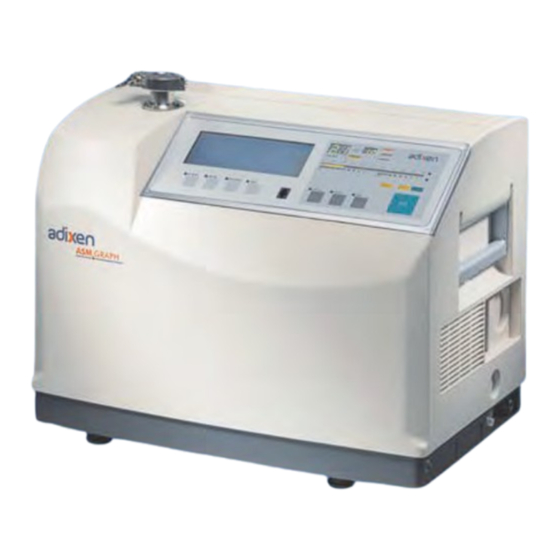
ASM GRAPH D+
User manual
Adixen ASM GRAPH D+ User Manual
Helium leak detector
Hide thumbs
1
2
3
4
5
6
7
8
9
10
11
12
13
14
15
16
17
18
19
20
21
22
23
24
25
26
27
28
29
30
31
32
33
34
35
36
37
38
39
40
41
42
43
44
45
46
47
48
49
50
51
52
53
54
55
56
57
58
59
60
61
62
63
64
65
66
67
68
69
70
71
72
73
74
75
76
77
78
79
80
81
82
83
84
85
86
87
88
89
90
91
92
93
94
95
96
97
98
99
100
101
102
103
104
105
106
107
108
109
110
111
112
113
114
115
116
117
118
119
120
121
122
123
124
125
126
127
128
129
130
131
132
133
134
135
136
137
138
139
140
141
142
143
144
145
146
147
148
149
150
151
152
153
154
155
156
157
158
159
160
161
162
163
164
165
166
167
168
169
170
171
172
173
174
175
176
177
178
179
180
181
182
183
184
185
186
187
188
189
190
191
192
193
194
195
196
197
198
199
200
201
202
203
204
205
206
207
208
209
210
211
212
213
214
215
216
217
218
219
220
221
222
223
224
225
226
227
228
229
230
231
232
233
234
235
236
237
238
239
240
241
242
243
244
245
246
247
248
249
250
251
252
253
254
255
256
257
258
259
260
261
262
263
264
265
266
267
268
269
270
271
272
273
274
275
276
277
278
279
280
281
282
283
284
285
286
287
288
289
290
291
292
293
294
295
296
297
298
299
300
301
302
303
304
305
306
307
308
309
310
311
312
313
314
315
316
317
318
319
320
321
322
323
324
325
326
327
328
329
330
331
332
333
334
335
336
Table Of Contents
337
page
of
337
Go
/
337
Contents
Table of Contents
Troubleshooting
Bookmarks
Table of Contents
General Contents
Introduction Detailed Contents
Introduction to the ASM 142 Series
ASM 142 Detector Operating Principle
Vacuum Circuit
Stand-By Mode
Roughing Mode
Gross Leak Test Mode
Normal Test Mode
Sniffing Test Mode
ASM 142 D Detector Operating Principle
ASM 142 Graph D+ Detector Operating Principle
Analyzer Cell Operating Principle
Description
Design and Manufacture
Overview
Testing Methods
Helium Concentration and Signal Displayed
Spray Method
Sniffer Method
Bombing Method
About Helium and Hydrogen
Helium and Leak Detection
Operator Interface: Control Panel
Options
Which Options for Which Model?
Automatic Test Chambers
Metal Seals
Languages
Inlet Port
Roughing System
Interface Board
Test of Gas Line
Stainless Steel Cover
Control Panel with Graphic Interface
Control Panel Racks
Sniffing
Cables Lengths
Which Accessories for Which Model?
Accessories
Remote Control
Long Distance Sniffer Probe
10 M/30 Feet LDS Extension
Headphone Connector
Transport Cart
Foot Pedal for Cycle
Calibrated Helium Leaks
Calibration Accessory
Spray Probe
Inlet Adaptor
Printer
Inlet Filters
Short Distance Sniffer Probe
Bombing Chamber
Test Chambers
Neutral Gas Vent Line Kit
4 Swiveling Wheels Kit
Covered Sniffer Probe and Remote Control Kit
Bottle Handle for Cart
Built-In Mini-Printer
2005 IS Pump
Pressure Measurement Kit
Ventilation Kit
ASM 142 Technical Characteristics
ASM 142 D - ASM Graph D+ Technical Characteristics
Dimensions (MM/Inch)
Installation Detailed Contents
Safety Instructions
Generalities
Pump Labels
Leak Detector Labels
Contact the Manufacturer in Case of Emergency
Unpacking - Storage - Transportation
Precautionary Measures for the Leak Detector Transportation
ASM 142 Graph D+
Supplies
Fixed Mounting
Precautionary Measures for the Leak Detector Installation
Neutral Gas Purge and Inlet Vent Connection
Products Concerned
Connection to the Leak Detector
Use
Gas Characteristics
Quality/Purity
Neutral Gas Purge
Neutral Gas Purge Installation (Accessory) ASM 142
Object
Material
Installation
Connecting the Detector to the Installation
Connecting the Detector to the Installation: ASM Graph D+
Controlling the Detector with the I/O Interface
24 V DC Power Supply
Controlling the Detector with a PC Computer through the RS 232 Interface
Connecting the Detector Directly to a Printer or Another Device
Tickets Available
Configuration Ticket
Calibration Ticket with Internal Calibrated Leak
Calibration Ticket with External Calibrated Leak
Calibration Checking Ticket with Internal Leak
Test Ticket
Check the Oil Level of the Rotary Vane Pump
Check Power Voltage
Before Starting up the Leak Detector
Operation Detailed Contents
Factory Configuration of the Leak Detector Parameters
Parameters Configuration
Operating Principle of the Control Panel
Graphic Interface Option
Control Keys
Menu Selection Access Keys
Parameter Function Keys
Description of Access Keys
Values Adjustment with the Control Panel
Setting and Maintenance Part Presentation of the Control Panel
Levels
To Change User Interface Level
Which Is Your User Interface Level?
Parameters Setting and Application Depending on Level and Display of the User Interface
Access to Level - Password
Change Password
Summary of Screens
Other Menu
Set Point Menu
Spectro Menu
Starting up / Switching off the Leak Detector
Starting up after an Unused/Storage Period
Starting up the Leak Detector
Switching off the Leak Detector
Recommended Procedure
How to Use the Leak Detector
Sniffing Test Method
Hard Vacuum Test Method
Operation of the Leak Detector
Hard Vacuum Test
Starting a Test Cycle
Leak Value Display
Ending a Test Cycle
Venting the Part or Installation Tested
Sniffer Probe Clogged Reject Point
Starting a Sniffing Test
Ending a Sniffing Test
Procedure with User Level
Adjust Vacuum/Sniffing Alarm Reject Point
Purpose of the Sniffer Probe Clogged Reject Point
Table of Contents
Basic Internal Calibration of the Leak Detector
Calibration of the Leak Detector
Purpose of the Internal Calibration
When Should an Internal Calibration be Performed?
Internal Calibrated Leak
Internal Calibration with the Internal He Calibrated Leak
Automatic Internal Calibration Procedure
Basic Internal Calibration of the Leak Detector
On Request Calibration Checking
On Request Internal Calibration Procedure
Internal Calibration with an External Calibrated Leak
Basic Internal Calibration of the Leak Detector
Activation/ Deactivation of the Internal Calibration
Advanced Internal Calibration of the Leak Detector
Checking Function
Parameters Setting
Checking Function with an External Calibrated Leak
Purpose of the External Calibration
External Calibration of the Leak Detector
External Calibrated Leak
Digital and Analog Display
External Calibration Procedure
Recalibration
About Sniffing Test Mode
Target Value Determination
Definition
Activate/Deactivate the Correction Factor VACUUM/SNIF COR Adjustment
Correction Factor
General Notes (in Vacuum or Sniffing Test Mode)
Calibrated Leak Values Programming
Different Types of Calibrated Leaks
Leak Location Selection
Programming the Calibrated Leak Parameters
Adaptor for Calibrated Leak in Sniffing Mode
How to Use the Adaptor ?
Remote Control Interface
Analog and Digital Displays
Remote Control Choice
Remote Control Connecting
Use and Display
External Calibration
Inlet Vent
Internal Calibration
External Loudspeaker
Headphone
Headphone and Loudspeaker
Level Adjustment
Configuration
3 Masses Option
Calibration in Hydrogen or Helium 3
Gas Selection
Purpose
Automatic Standby Screen
Graphic Interface Purpose
Leak Detector Software Version
Use Caution
Control Panel Interface
Change of Interface
Operating Principle of the Graphic Interface
Operating Principle of the Standard Interface
At the Leak Detector Start up
During the Leak Detector Use
Selection of the Graphic Interface Use Mode
Graphic Interface Description
Selection Keys
Graphic Interface Setting
Menus Description
Contrast Adjustment
Memorized Graph
Recording
Point Measure
Memorized Graphs Saving
Animated Synoptic
Synoptic Reading
Long Distance Sniffer Probe and Helium Spray Gun
Air Vent Purpose
Choices Proposed to the Operator
Inlet: Air Vent
Air Vent Adjustment
Air Vent Opening / Closing
Inlet: Gas Line Option
Activate/Deactivate the Bargraph Zoom
Bargraph Zoom
Analog Display
Remote Control and Control Panel
Zero Function and Bargraph Zoom
Adjustment
Audio Alarm Definition
Digital Voice Definition
Sound Level
Activate / Deactivate the Cycle End
Purpose of the Cycle End
Zero Function
Activate the Zero Function
Activation/Deactivation of the Background
Deactivate the Zero Function
Display
Zero Not Activated
Memo Function
Zero Activated
Activate/Deactivate the Memo Function
Display Timer
Activate/Deactivate the Helium Pollution Prevention
Date - Time - Language - Unit
A Help for Control Panel Utilization/Access
Adjustment Procedure
Helium Pollution Prevention
Fault / Information Indicator and Display
Fault and Information
Faults
Minor Fault
Critical Failure
Major Fault
List of Messages
Maintenance - Troubleshooting Detailed Contents
Table of Preventive Maintenance Intervals
Adjustment of the Counters
Maintenance Message
General Troubleshooting Guide
Symptoms Description
To Access to the Interactive Application
To Print the Sheets D 300 and D 400
Maintenance Sheets Detailed Contents
Icons Used
Maintenance Operations Instruction
Working Conditions
Access Level 1
Access to the Internal Components ASM 142 / ASM 142 S
Removable Cover
Access to the Board P0326 and P0330
Access to the Internal Calibrated Leak
Disassemble the Main Block
Cart Handle Removing
Remove the Inlet Port Clamp
Remove Upper the Cover. be Careful of the Front Panel Cable
Switch off the Machine by Setting the Main Switch to «0» and Disconnecting the Main Power
Unfasten the 4 Securing Screws and Their Washers Using a 5 MM allen Key. Use a 5Mm allen Wrench
If Necessary, Disconnect the 20 Points Connector
Open the «Clip» for Ribbon Cable
Access to the Internal Components ASM 142 D - ASM Graph D+
Molecular Pump Connector
ACP Secondary Pump
Transportation
Safety Questionnaire
Sending of a Leak Detector for Reparation to a Service Center
Packaging
Basic Maintenance of the Analyzer Cell
Special Precautions
Cell Disassembly
Cleaning the Body
Disassemble the Filaments
Disassemble the Electron Collector
Replace the Electron Collector and the Filaments
Tighten All the Connection Screws
Reassemble the Flange
Tighten All the Securing Screws
Verification of the Electrical Zero
Restart and Check Proper Operation of the Analyzer Cell
Switch On/Off the Filament
Reset the Filament Information Timer
Valves Installation and Maintenance
Valves Identification
Vacuum Activated Valves (Depression Valves)
Minisol and Bacosol Valves
Dismantling
Cleaning
Seal Preparation
Assembly of Minisol Valves with Valve Block
Fitting Connection Exchange
Reassembly
Screw Tightening Torque
Test after Installation
Replacement of the Internal Calibrated Leak
Purpose of the Calibrated Internal Leak
Frequency of the Internal Leak «Recalibration»
How to Recalibrate the Internal Leak
Installation of a New Internal Calibrated Leak
Intensive Use of the Detector
Replacement of the Remote Control
Remote Control Defective
Remote Control Box Exchange
AMD1 Diaphragm Pump Breakdown View
AMD1 Diaphragm Pump Maintenance
Replacing Check Valves and Diaphragms
Disassembling the Pump from Its Support
Connector Disassembly
Check Valve Disassembly
Diaphragm Disassembly
Diaphragm Reassembly
Check Valve Reassembly
Connector Reassembly
Reassembling the Pump on Its Support
First Start up after Delivery
Starting in the Cold State
Restarting after Stop
Starting of the Molecular and Turbomolecular Pumps
Greasing Molecular and Turbomolecular Pumps
Disassemble the Pump
Accessing the Bearings
Using the Grease Syringe
Greasing the Front Bearing
Greasing the Rear Bearing
«Running In» the Pump after Relubrication
Adjust the Correspondance between the Different Test Modes
Bearing Opposite the Pumping Cell
Bearing on Pumping Cell Side
Add Oil
Check the Oil Level of the Roughing Pump
Primary Pump Maintenance
For Oil Contamination, Drain the Pump
For Dirty Oil, Rinse the Pump
Remove and Change the Oil Mist Eliminator
Components Detailed Contents
Spare Parts - Instructions of Use
Replacement of Parts and Use of Non Genuine Parts
AVTF Customer Service Offer
Tools ASM 142
Monitoring and Display ASM 142
Power and Electrical Supply ASM 142
Automatic Control System and Electronic Circuits ASM 142
Measurement ASM 142
Pumping ASM 142
Valves ASM 142
Pipes - Connections - Seals ASM 142
Cover ASM 142
Options and Accessories ASM 142
Tools ASM 142 D
Monitoring and Display ASM 142 D
Power and Electrical Supply ASM 142 D
Automatic Control System and Electronic Circuits ASM 142 D
Measurement ASM 142 D
Pumping ASM 142 D
Valves ASM 142 D
Pipes - Connections - Seals ASM 142 D
Cover ASM 142 D
Options and Accessories ASM 142 D
Pictures of Components
Tools
Monitoring and Display
Power and Electrical Supply
Automatic Control System and Electronic Circuits
Measurement
Pumping
Valves
Pipes - Connections - Seals
Cover
Options and Accessories
Appendix Detailed Contents
Wiring Diagrams - ASM 142
Wiring Diagrams - ASM 142 D
Analog Outputs
Long Distance Sniffer Probe User Manual
Dimensions
Technical Characteristics
Use Precautions with the Flexible Sniffer Probe
Flow Adjustment
Available Spare Parts
Filter Exchange
Needle Replacement
O'ring Installation
"Sniffer Probe Clogged" Message
Adaptor for Calibrated Leak
Helium Spray Gun User Manual
Use Precaution
Spare Parts
Tools Contents
ASM View Supervisory Software
Downloader
ASM Graph Downloader Software
Detectors Concerned
ASM Dialogue Software
Interface
Advertisement
Quick Links
1
Use
Download this manual
See also:
Operating Manual
ASM 142 / 142 D
ASM GRAPH / GRAPH D / GRAPH D+
HELIUM LEAK DETECTOR
Use
r's Manual
Table of
Contents
Previous
Page
Next
Page
1
2
3
4
5
Advertisement
Table of Contents
Troubleshooting
Maintenance - Troubleshooting Detailed contents
181
General troubleshooting guide
185
Need help?
Do you have a question about the ASM GRAPH D+ and is the answer not in the manual?
Ask a question
Questions and answers
Subscribe to Our Youtube Channel
Related Manuals for Adixen ASM GRAPH D+
Security Sensors Adixen ASM 142 User Manual
Helium leak detector (337 pages)
Security Sensors Adixen ASM 142 D User Manual
Leak detector (11 pages)
Security Sensors Adixen ASM 142 Operating Manual
(12 pages)
Security Sensors Adixen ASM 182 TD PLUS User Manual
Helium leak detector (87 pages)
Security Sensors Adixen ASM 310 Operating Instructions Manual
Portable leak detector (145 pages)
Table of Contents
Save PDF
Print
Rename the bookmark
Delete bookmark?
Delete from my manuals?
Login
Sign In
OR
Sign in with Facebook
Sign in with Google
Upload manual
Upload from disk
Upload from URL


Need help?
Do you have a question about the ASM GRAPH D+ and is the answer not in the manual?
Questions and answers