Table of Contents
Advertisement
Advertisement
Chapters
Table of Contents

Summarization of Contents
SERVICE MANUAL
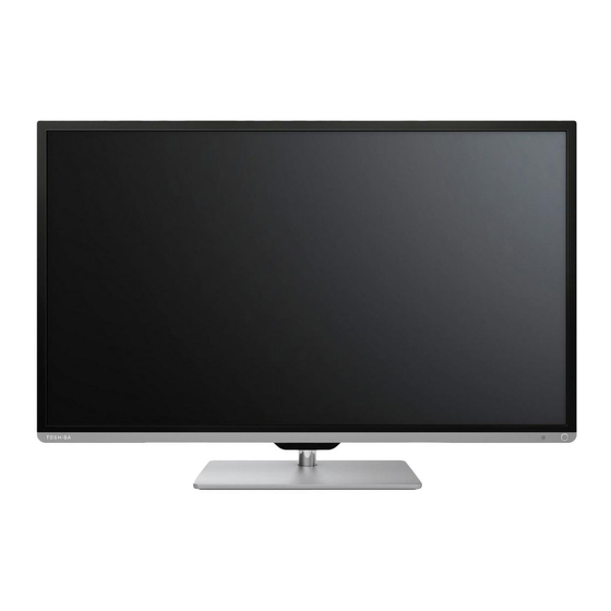
LCD Color Television
Specifies the type of television this service manual covers.
40L7363RK / 40L7356RK
Identifies the specific model numbers for which this manual is applicable.
IMPORTANT NOTICE
WARNING
States that information shall not be modified or altered without prior written consent from Toshiba.
LEAD-FREE SOLDER
WARNING
Product is manufactured using lead-free solder and prohibits lead-based solder for repairs.
SAFETY INSTRUCTION
Safety Precaution
Precautions to be observed before servicing this chassis, emphasizing service by qualified personnel.
SERVICE MODE
ENTERING SERVICE MODE
Step-by-step instructions on how to enter the service mode using the remote control and TV panel.
KEY FUNCTION IN THE SERVICE MODE
Details the functions of buttons and key entries within the service mode menu.
ADJUSTING ITEMS IN THE SERVICE MODE
Lists items that can be adjusted within the service mode, with their descriptions.
HOTEL MODE
ENTERING HOTEL MODE MENU
Provides the operation steps to display the Hotel Mode menu.
OPERATING HOTEL MODE MENU
Explains how to enable and adjust settings within the Hotel Mode menu.
HOTEL CLONE
Copying the Settings From TV To USB Drive
Step-by-step guide for copying TV settings to a USB drive.
EXPLODED VIEW
40L7363RK
Exploded view diagram and parts list for the 40L7363RK model.
SAFETY PRECAUTION
Highlights critical parts for safety and the need for identical replacements.
40L7356RK
Exploded view diagram and parts list for the 40L7356RK model.
SET ID and PANEL ID
Panel vendor Information (Panel ID)
Table mapping markings to panel vendors and their corresponding Panel IDs.
Model/Panel Information
Lists models with their SET ID, Panel ID, and Panel Vendor information.
MAIN BOARD EXCHANGE
Updating of Software and Model Setting
Procedures for updating Application SW (Firmware) and Model Setting after main board exchange.
129. DDR3 SDRAM POWER
Add VTT Regulator and Related components.
Details the addition of a VTT regulator and associated components for DDR3 power.
700. LED/RMT/KEY IF
Standby PWM
Details the standby PWM signal configuration.
Control Panel image
Illustrates the control panel layout with key functions.
750. TUNER
ANALOG TUNER
Schematic for the analog tuner section.
PC/HDMI Audio In(reserved)
Details PC/HDMI audio input connections, reserved for future use.
L/R In(reserved)
Details Left/Right audio input connections, reserved for future use.
751. TUNER IF_AGC
IF Filter
Schematic of the intermediate frequency (IF) filter.
AGC
Schematic for the automatic gain control (AGC) circuit.
I2C & BUS SW
Schematic for I2C communication and bus switching functions.
791. CI POWER/CONNECTOR
CI POWER
Schematic for CI power supply and related components.
CI CONNECTOR
Pin assignment details for the CI connector.
KEYPAD
The circuit Diagram of Tact switch
Illustrates the circuit diagram for tact switches, including power key.
Control Panel image
Provides an image of the control panel with labels for keys.
IR/LED
Brightness sensor
Schematic for the brightness sensor component.
Note
modify note for KEYPAD
Notes on revisions for the keypad section, including DFM and bar-code positions.
modify note for IR
Notes on revisions for the IR section, including mirrored sensors and bar-code positions.
Release Notice
Contents
Lists the main sections and their corresponding page numbers.
Purpose
Defines the functional specification and characteristics of 40” TV LIPS.
Input Characteristics
Details the electrical characteristics of the power supply's input.
Leakage Current
Specifies leakage current limits according to UL and IEC standards.
Output characteristics
Details the performance characteristics of the power supply's outputs.
Output Protections
Details over voltage protection mechanisms and their status.
LED Characteristics
Details output and input ratings related to LED characteristics.
Environmental
Specifies environmental operating and storage conditions.
Products Safety Approvals
Lists power supply safety regulations like UL 60065 and IEC/EN 60065.
Insulation resistance
Specifies test requirements and judgment criteria for insulation resistance.
7. Mechanical Drawing
Power supply drawing
Provides a mechanical drawing of the power supply unit.
8. Connectors Type and Pins Assignment
Connected to Power Cord (CN1)
Lists pin assignments for the power cord connector.
Connected to Main Board (CN3)
Details pin assignments for the connector to the main board.
Connected to LED Light Bar (CN3)
Details pin assignments for the connector to the LED light bar.
10. PCB Label Printing
DARFON PCB Label Coding Rule (Label Size: 28*8mm)
Explains the coding rules for DARFON PCB labels, including size and data format.


Need help?
Do you have a question about the 40L7356RK and is the answer not in the manual?
Questions and answers