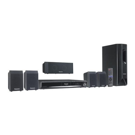
Panasonic SB-HW460 Service Manual
Dvd home theater sound system
Hide thumbs
Also See for SB-HW460:
- Operating instructions manual (44 pages) ,
- Operating instructions manual (36 pages) ,
- Operating instructions manual (36 pages)
Table of Contents
Advertisement
Notes: This model's CD/DVD mechanism is DLS6. Please refer to the original service manual (Order No.
MD0801003CE) for this mechanism.
Specifications
Main unit SA-PT460EB/EG
GENERAL
Power supply:
Power consumption:
Power consumption in standby mode:
Dimensions (W×H×D):
Mass:
Operating temperature range:
Operating humidity range:
AMPLIFIER SECTION
RMS Output Power: Dolby Digital Mode
Front Ch:
125 W per channel (3 Ω), 1 kHz, 10% THD
Surround Ch:
125 W per channel (3 Ω), 1 kHz, 10% THD
Center Ch:
250 W per channel (6 Ω), 1 kHz, 10% THD
DVD Home Theater Sound System
AC 230-240 V, 50 Hz
This unit 135 W
approx. 0.4 W
430 mm×63 mm×327 mm
This unit 3.4 kg
+5 °C to +35 °C
5 % to 90 % RH
(no condensation)
SA-PT460EB
SA-PT460EG
Colour
(K).......................Black Type
(S).......................Silver Type (For EG Only)
Subwoofer Ch:
250 W per channel (6 Ω), 100 Hz, 10 % THD
Total RMS Dolby Digital mode power:
DIN Output Power: Dolby Digital Mode
Front Ch:
75 W per channel (3 Ω), 1 kHz, 1% THD
Surround Ch:
75 W per channel (3 Ω), 1 kHz, 1% THD
Center Ch:
145 W per channel (6 Ω), 1 kHz, 1% THD
Subwoofer Ch:
145 W per channel (6 Ω), 100 Hz, 1 % THD
Total DIN Dolby Digital mode power:
FM TUNER, TERMINALS SECTION
Preset Memory:
Frequency Modulation (FM)
ORDER NO. MD0801001CE
1000 W
590 W
FM 30 stations
Advertisement
Table of Contents
Troubleshooting

Related Manuals for Panasonic SB-HW460


Summarization of Contents
Specifications
General
General specifications including power supply, consumption, dimensions, mass, and operating conditions.
Amplifier Section
Details RMS and DIN output power specifications for Dolby Digital Mode for all channels.
FM Tuner, Terminals Section
FM tuner specifications including preset memory and frequency modulation.
Safety Precautions
General Guidelines
Provides general guidelines for servicing, including lead dress, protective device installation, and leakage current checks.
Leakage Current Cold Check
Outlines the procedure for measuring resistance between the AC plug and exposed metallic parts when the unit is unplugged.
Leakage Current Hot Check
Details the procedure for measuring AC voltage across a resistor connected between an exposed metallic part and earth ground when the unit is powered on.
Before Repair and Adjustment
Advises on discharging AC capacitors before repair and cautioning against short-circuiting.
Protection Circuitry
Explains conditions under which protection circuitry may operate, such as no sound or sound stopping during playback.
About Lead Free Solder (PbF)
Service Caution based on Legal Restrictions
Discusses the use of lead-free solder for environmental conservation and provides service cautions for repair work.
Handling Precautions for Traverse Unit
Cautions to Be Taken in Handling the Optical Pickup Unit
Advises on avoiding static discharge damage to the laser diode and handling the optical pickup unit carefully.
Grounding for Electrostatic Breakdown Prevention
Details methods for grounding the worktable and human body to prevent electrostatic discharge damage.
Operation Procedures
Remote Control Key Buttons Operations
Explains the function of each key button on the remote control unit for operating the system.
Audio and Video Connection
Basic Setup
Illustrates the basic setup for connecting the unit to a TV using SCART cables for audio and video.
Connecting to a Television with HDMI Terminal
Details the connection procedure and features of using an HDMI terminal for optimal picture and audio quality.
Disc Information
Disc Playability (Media)
Lists commercial and recorded discs that the unit can play, along with remarks on compatibility and recording formats.
Self-Diagnosis and Special Mode Setting
Service Mode Summary Table
Summarizes various service modes accessible via button combinations on the main unit and remote control for checking.
Service Mode Table
Provides details on activating specific service modes through button combinations on the main unit and remote control.
DVD Self Diagnostic Function-Error Code
Mechanism Error Code Table
Lists mechanism error codes, their diagnosis contents, descriptions of errors, automatic FL display, and remarks.
Sales Demonstration Lock Function
Setting
Explains how to activate the Sales Demonstration Lock function to prevent disc removal and disable ordinary operations.
Service Precautions
Recovery after the DVD player is repaired
Details the recovery process after replacing FLASH ROM IC or DVD Module P.C.B. to optimize drive performance.
Firmware version-up of the DVD player
Explains how to renew the DVD player's firmware to improve quality, operability, and playability.
DVD Module P.C.B. Reset
Provides procedures for resetting the DVD Module P.C.B. when error code "DVD F897" is displayed after replacement.
Assembling and Disassembling of DVD Mechanism Unit
Disassembling Procedures
Outlines the procedures for disassembling the CD traverse unit of the DVD mechanism.
Disassembly of CD traverse
Details the steps for releasing guides, lifting, and sliding out the CD traverse unit from the DVD mechanism.
Assembling Procedure
Assembly of CD traverse
Provides instructions for assembling the CD traverse unit into the DVD mechanism chassis, including fixing bosses and guides.
Service Position
Checking & Repairing Main P.C.B.
Details steps to remove the top cabinet for servicing the Main Printed Circuit Board.
Checking & Repairing D-Amp P.C.B.
Provides instructions for removing the top cabinet and rear panel to access the D-Amp Printed Circuit Board.
Measurements and Adjustments
Service Tools and Equipment
Lists the service tools and equipment required for measurements and adjustments, including test discs and drivers.
Important points in adjustment
Highlights key considerations for optical and electrical adjustments, emphasizing anti-static measures and procedure adherence.
Storing and Handling of Test Discs
Provides guidelines for the proper storage and handling of test discs to ensure accurate adjustments and prevent damage.
Optical adjustment
Optical pickup tilt adjustment
Details the procedure for optical pickup tilt adjustment, including playing test discs and adjusting screws to minimize jitter.
Voltage and Waveform Chart
DVD Module P.C.B.
Presents a chart of voltage and waveform measurements for various points on the DVD Module P.C.B. under different modes.
Waveform Chart
Waveform 1
Displays waveform examples for various ICs, showing voltage and time division for signal analysis.
Block Diagram
System Control
Shows the system control block diagram, illustrating the interaction between the Micro-processor and other modules.
Schematic Diagram
DVD Module Circuit
Displays the schematic diagram for the DVD Module circuit, detailing component connections and signal paths.
Printed Circuit Board
DVD Module P.C.B.
Shows the layout of the DVD Module Printed Circuit Board (PCB) on both sides, indicating component placement.
Basic Troubleshooting Guide
Troubleshooting Guide for F61 and/or F76
Illustrates checking procedures for errors F61 and F76, focusing on SMPS, D-Amp, and Power Supply PCBs.
Part Location
SMPS P.C.B.
Identifies the location of key components on the SMPS Printed Circuit Board, including transistors, thermistors, and feedback circuits.
Terminal Function of ICs
IC2001 (C2CBYY00534): IC System Control
Lists the terminal names, I/O, and functions for the IC System Control (IC2001).
IC1701 (MFI341S2095): IC Ipod Video
Details the terminal names, I/O, and functions for the IC Ipod Video (IC1701).
IC6901(C0HBB0000057): IC FL Driver
Lists the terminal names, I/O, and functions for the IC FL Driver (IC6901).
Exploded Views
Cabinet Parts Location
Shows an exploded view of the unit's cabinet, illustrating the location of various parts for disassembly and assembly.
Need help?
Do you have a question about the SB-HW460 and is the answer not in the manual?
Questions and answers