Table of Contents
Advertisement
TopPage
[1]
SPECIFICATION ........................................... 1-1
[2]
EXTERNAL DIMENSION .............................. 1-3
[3]
WIRING DIAGRAM ....................................... 1-4
[4]
ELECTRICAL PARTS.................................... 1-4
[1]
BLOCK DIAGRAMS ...................................... 2-1
[2]
[3]
FUNCTION .................................................... 2-7
[4]
OPERATION MANUAL................................2-16
[1]
OPERATIONS ............................................... 3-1
[2]
THERMISTOR ERROR................................. 3-3
[3]
ACTERISTICS............................................... 3-5
[4]
UNIT INDEPENDENTLY ............................... 3-6
Parts marked with "
" are important for maintaining the safety of the set. Be sure to replace these parts with specified ones for maintaining the
safety and performance of the set.
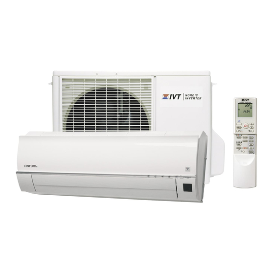
SERVICE MANUAL
SPLIT TYPE
AIR TO AIR HEAT PUMP
12LR-N
MODEL
09LR-N
In the interests of user-safety (Required by safety regulations in some
countries) the set should be restored to its original condition and only
parts identical to those specified should be used.
CONTENTS
[5]
[6]
OD.......................................................... . ....... 3-8
[7]
OUTDOOR UNIT CHECK METHOD ..... . ......3-11
[8]
TROUBLESHOOTING GUIDE .............. . ..... 3-14
CHAPTER 4. REFRIGERATION CYCLE
[1]
FLOW FOW REFRIGERANT ................ . ....... 4-1
[2]
STANDARD CONDITION ...................... . ....... 4-1
........ 2-3
[3]
PRESSURE IN 3-WAY VALVE............... . ....... 4-1
[4]
PERFORMANCE CURVES ................... . ....... 4-2
[1]
INDOOR UNIT ....................................... . ....... 5-1
[2]
CLUSTER UNIT..................................... . ....... 5-4
[3]
OUTDOOR UNIT ................................... . ....... 5-6
This document has been published to be used for
after sales service only.
The contents are subject to change without notice.
12LRN
........ 3-6
Advertisement
Table of Contents
Troubleshooting

Summarization of Contents
CHAPTER 1. SPECIFICATION
[1] SPECIFICATION
Detailed technical specifications for the air to air heat pump models.
[2] EXTERNAL DIMENSION
Provides detailed physical dimensions for the indoor and outdoor units.
[3] WIRING DIAGRAM
Illustrates the electrical wiring connections for both indoor and outdoor units.
[4] ELECTRICAL PARTS
Lists and identifies the electrical components used in the unit.
CHAPTER 2. EXPLAMATION OF CIRCUIT AND OPERATION
[1] BLOCK DIAGRAMS
Visual representation of the functional blocks and signal flow for the indoor unit.
[2] MICROCOMPUTER CONTROL SYSTEM
Explains the microcontroller's role in operating the air conditioner.
[3] FUNCTION
Details the various operational functions and protection mechanisms of the unit.
[4] OPERATION MANUAL
Instructions on how to operate the air conditioner using the remote control.
CHAPTER 3. FUNCTION AND OPERATION OF PROTECTIVE PROCEDURES
[1] PROTECTION DEVICE FUNCTIONS AND OPERATIONS
Explains the protective functions and their operational responses.
[2] AIR TO AIR HEAT PUMP OPERATION IN THERMISTOR ERROR
Describes how the unit operates when thermistor errors occur.
[3] THERMISTOR TEMPERATURE CHARACTERISTICS
Provides temperature-resistance characteristics for various thermistors.
[4] HOW TO OPERATE THE OUTDOOR UNIT INDEPENDENTLY
Instructions for operating the outdoor unit in a standalone cooling mode.
[5] GENERAL TROUBLESHOOTING CHART
1. Indoor unit
Troubleshooting guide for issues related to the indoor unit's power and operation.
2. Indoor unit fan does not operate
Diagnosing problems when the indoor unit fan fails to operate.
3. Indoor unit fan speed does not change
Troubleshooting steps for issues with the indoor fan speed control.
4. Remote control signal is not received
Steps to diagnose why the remote control is not communicating with the unit.
5. Louvers do not move
Troubleshooting guide for when the air louvers fail to adjust their position.
6. There is noise in TV/radio
Diagnosing and resolving radio or TV interference caused by the unit.
7. Malfunction occurs
General troubleshooting for unit malfunctions.
8. Compressor does not start
Steps to diagnose why the compressor is not starting.
9. Operation stops after a few minutes and restarts, and this process repeats
Troubleshooting for intermittent operation cycles and restarts.
[6] MALFUNCTION (PARTS) CHECK METHOD
1. Procedure for determining defective outdoor unit IPM/compressor
Flowchart for diagnosing IPM and compressor issues.
2. Procedure for determining defective expansion valve
Steps to check the expansion valve for defects.
3. Diode bridge check method
Method for checking the diode bridge component using a tester.
4. Inverter electrolytic capacitor (C9, C10) check method
Procedure for checking the inverter electrolytic capacitors.
5. IPM check method
Method for checking the IPM (Intelligent Power Module) for proper function.
6. DC Over Current Error (6-0 error)
Troubleshooting flowchart for DC overcurrent errors.
[7] OUTDOOR UNIT CHECK METHOD
1. Checking procedures
Step-by-step inspection process for the outdoor unit.
2. Troubleshooting of outdoor unit electric components
Diagnosing electrical component issues in the outdoor unit.
3. Caution in checking printed circuit boards (PWB)
Important safety precautions when checking printed circuit boards.
[8] TROUBLESHOOTING GUIDE
1. Self-Diagnosis Function
Explains how to activate and interpret the unit's self-diagnostic modes and indicators.
CHAPTER 4. REFRIGERATION CYCLE
[1] FLOW FOW REFRIGERANT
Illustrates the path of refrigerant through the indoor and outdoor units.
[2] STANDARD CONDITION
Specifies the standard conditions under which performance is measured.
[3] TEMPERATURE AT EACH PART AND PRESSURE IN 3-WAY VALVE
Lists temperatures and pressures at various points in the system.
[4] PERFORMANCE CURVES
Graphs showing performance characteristics based on outdoor air temperature.
CHAPTER 5. DISASSEMBLY PROCEDURE
[1] INDOOR UNIT
Detailed procedure for disassembling the indoor unit.
[2] THE WIRE GUARD AND THE PLASM-CLUSTER UNIT
Steps for removing wire guards and the plasmacluster unit.
[3] OUTDOOR UNIT
Detailed procedure for disassembling the outdoor unit.
PARTS GUIDE
[1] INDOOR UNIT PARTS
Illustrated list of all parts belonging to the indoor unit.
[2] ACCESSORY PARTS
List of accessory parts included with the unit, like manuals and remotes.
[3] OTHER PARTS
Miscellaneous parts not categorized under main units or accessories.
[4] INDOOR PACKING PARTS
Components related to the packaging of the indoor unit.
[5] OUTDOOR UNIT PARTS
Illustrated list of all parts belonging to the outdoor unit.
[6] OTHER PARTS
Miscellaneous parts not categorized under main units or accessories.
[7] OUTDOOR PACKING PARTS
Components related to the packaging of the outdoor unit.


Need help?
Do you have a question about the 12LR-N and is the answer not in the manual?
Questions and answers