Advertisement
S
ervice
M anua l
BRIDGEABLE POWER AMPLIFIER
GM-X622
GM-X622
GM-X622
GM-X522
CONTENTS
1. SAFETY INFORMATION ............................................2
2. EXPLODED VIEWS AND PARTS LIST .......................2
3. SCHEMATIC DIAGRAM .............................................6
4. PCB CONNECTION DIAGRAM ................................12
5. ELECTRICAL PARTS LIST ........................................14
6. ADJUSTMENT..........................................................17
PIONEER ELECTRONIC CORPORATION
PIONEER ELECTRONICS SERVICE INC.
PIONEER ELECTRONIC [EUROPE] N.V.
PIONEER ELECTRONICS ASIACENTRE PTE.LTD. 501 Orchard Road, #10-00, Wheelock Place, Singapore 238880
C PIONEER ELECTRONIC CORPORATION 1998
GM-X622/X1R/UC
4-1, Meguro 1-Chome, Meguro-ku, Tokyo 153-8654, Japan
P.O.Box 1760, Long Beach, CA 90801-1760 U.S.A.
Haven 1087 Keetberglaan 1, 9120 Melsele, Belgium
X1R/EW
X1R/ES
X1R/UC
7. GENERAL INFORMATION .......................................18
7.1 IC .........................................................................18
7.2 DISASSEMBLY ...................................................19
7.3 BLOCK DIAGRAM ..............................................20
8. OPERATIONS AND SPECIFICATIONS.....................21
K-ZED. FEB.1998 Printed in Japan
ORDER NO.
CRT2190
X1R/UC
Advertisement
Table of Contents

Related Manuals for Pioneer GM-X622 X1R/ES


Summarization of Contents
Exploded Views and Parts List
2.1 PACKING
Details the packing components and their part numbers.
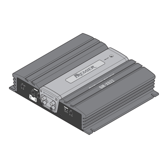
2.2 EXTERIOR
Provides an exploded view of the external components of the amplifier.
Schematic Diagram
3.1 OVERALL CONNECTION DIAGRAM
Shows the overall wiring and connections for the amplifier unit.
PCB Connection Diagram
4.1 AMP UNIT
Illustrates the PCB layout and component placement for the amplifier unit.
General Information
7.1 IC
Details the pinout and internal schematic of the PA2027A integrated circuit.
7.2 DISASSEMBLY
Provides step-by-step instructions for taking the unit apart safely.
Operations and Specifications
8.1 SPECIFICATIONS
Lists technical specifications such as power output, impedance, and frequency response.
Operations
Power Indicator
Explains the function of the power indicator light on the amplifier.
Gain Control
Describes how to adjust the input gain for optimal sound levels.
Bass Boost Level Control
Details how to adjust the bass boost intensity.
Bass Boost Frequency Control
Explains how to select the frequency range for bass boost.
Cut Off Frequency Control
Describes how to set the crossover frequency for filters.
LPF/HPF Select Switch
Guides on selecting filter types and audio ranges for speaker output.
Need help?
Do you have a question about the GM-X622 X1R/ES and is the answer not in the manual?
Questions and answers