Table of Contents
Advertisement
www.enindel.com
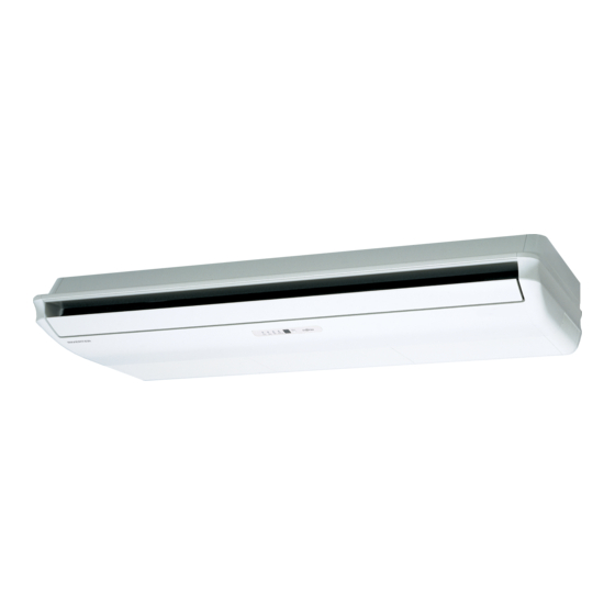
SPLIT TYPE
AIR CONDITIONER
CEILING TYPE (50Hz)
Indoor unit
ABYG36LRTA
ABYG45LRTA
ABYG54LRTA
C O NTE N TS
SPECIFICATIONS . . . . . . . . . . . . . . . . . . .
DIMENSIONS. . . . . . . . . . . . . . . . . . . . . . .
REFRIGERANT SYSTEM DIAGRAM . . . .
CIRCUIT DIAGRAM . . . . . . . . . . . . . . . . . .
INDOOR PCB CIRCUIT DIAGRAM . . . . . .
ERROR DETECTION. . . . . . . . . . . . . . . .
PARTS (INDOOR UNIT) . . . . . . . . . . . . .
PARTS (OUTDOOR UNIT) . . . . . . . . . . .
ACCESSORIES . . . . . . . . . . . . . . . . . . . .
Outdoor unit
AOYG36LATT
AOYG45LATT
AOYG54LATT
1
2
4
5
6
10
. . .
17
21
26
29
Advertisement
Table of Contents

Summarization of Contents
SPECIFICATIONS
ELECTRICAL DATA
Electrical characteristics of indoor and outdoor units, including capacity, power, and current.
NOISE LEVEL
Noise levels for indoor and outdoor units in cooling and heating modes at various settings.
COMPRESSOR AND REFRIGERANT
Details on the compressor type, refrigerant, and system charge.
FAN MOTOR
Specifications for indoor and outdoor unit fan motors, including speed and power.
DIMENSIONS
INDOOR UNIT DIMENSIONS
Detailed dimensions and diagrams for the indoor unit's physical size.
DIMENSIONS
OUTDOOR UNIT DIMENSIONS
Detailed dimensions and diagrams for the outdoor unit's physical size.
REFRIGERANT SYSTEM DIAGRAM
SYSTEM COMPONENTS AND FLOW
Diagram illustrating the refrigerant flow and key components in the system.
CIRCUIT DIAGRAMS
INDOOR UNIT WIRING
Wiring diagram detailing the electrical connections for the indoor unit.
OUTDOOR UNIT WIRING
Wiring diagram detailing the electrical connections for the outdoor unit.
INDOOR PCB CIRCUIT DIAGRAM
CONTROL UNIT AND PCB LAYOUT
Detailed circuit diagram for the indoor unit's control and printed circuit boards.
INDOOR UNIT MAIN PCB SCHEMATIC
MAIN PCB CIRCUIT DIAGRAM
Detailed schematic of the indoor unit's main printed circuit board.
INDOOR UNIT POWER SUPPLY PCB SCHEMATIC
POWER SUPPLY PCB CIRCUIT DIAGRAM
Detailed schematic of the indoor unit's power supply printed circuit board.
INDOOR UNIT INDICATOR PCB SCHEMATIC
INDICATOR PCB CIRCUIT DIAGRAM
Detailed schematic of the indoor unit's indicator printed circuit board.
OUTDOOR PCB CIRCUIT DIAGRAMS
INVERTER ASSEMBLY & P.F.C. PCB CIRCUITS
Circuit diagrams for Inverter Assembly and PFC PCB.
FILTERING & POWER CONTROL PCBS
Diagrams for Active Filter, Filter, and Capacitor PCBs.
TRANSISTOR & MAIN PCB CIRCUITS
Diagrams for Transistor and Main PCBs.
OUTDOOR UNIT MAIN PCB SCHEMATIC
MAIN PCB CIRCUIT DIAGRAM
Detailed schematic of the outdoor unit's main printed circuit board.
OUTDOOR UNIT TRANSISTOR PCB SCHEMATIC
TRANSISTOR PCB CIRCUIT DIAGRAM
Detailed schematic of the outdoor unit's transistor printed circuit board.
OUTDOOR UNIT ACTIVE FILTER PCB CIRCUIT - 1
ACTIVE FILTER PCB SCHEMATIC
Detailed schematic of the outdoor unit's active filter PCB (Part 1).
OUTDOOR UNIT ACTIVE FILTER PCB CIRCUIT - 2
ACTIVE FILTER PCB SCHEMATIC
Detailed schematic of the outdoor unit's active filter PCB (Part 2).
OUTDOOR UNIT FILTER PCB SCHEMATIC
FILTER PCB CIRCUIT DIAGRAM
Detailed schematic of the outdoor unit's filter printed circuit board.
OUTDOOR UNIT CAPACITOR PCB SCHEMATIC
CAPACITOR PCB CIRCUIT DIAGRAM
Detailed schematic of the outdoor unit's capacitor printed circuit board.
ERROR DETECTION
INDOOR UNIT AND WIRED REMOTE CONTROL ERROR CODES
Error codes for indoor unit and wired remote control, with descriptions.
TEST RUN PROCEDURES
PRE-TEST RUN CHECKS
Essential checks to perform before initiating a test run.
TEST RUN METHOD
Step-by-step guide for performing the unit's test run.
OPERATING PROCEDURES DURING TEST RUN
Instructions for operating the unit during the test run phase.
OUTDOOR UNIT ERROR CODE DISPLAY
ERROR CODE CHECK TABLE
Table detailing outdoor unit error codes and LED blinking patterns.
OUTDOOR UNIT PUMP DOWN OPERATION
PUMP DOWN PROCEDURE
Detailed steps for collecting refrigerant before unit servicing.
PUMP DOWN PREPARATION AND SAFETY
Pre-operation checks and safety precautions for pump down.
INDOOR UNIT PARTS LIST
MAIN UNIT COMPONENTS
Illustrated parts list for the indoor unit's main body and covers.
INDOOR UNIT DRAIN PAN AND FLAP PARTS
DRAIN PAN AND FLAP COMPONENTS
Illustrated parts list for the indoor unit's drain pan and flap assembly.
INDOOR UNIT FAN MOTOR PARTS
FAN MOTOR ASSEMBLY COMPONENTS
Illustrated parts list for the indoor unit's fan motor and related parts.
INDOOR UNIT LOUVER MECHANISM PARTS
LOUVER ASSEMBLY COMPONENTS
Illustrated parts list for the indoor unit's louver base and mechanism.
INDOOR UNIT CONTROL UNIT PARTS
CONTROL UNIT COMPONENTS
Illustrated parts list for the indoor unit's control unit and remote interface.
OUTDOOR UNIT PARTS LIST
EXTERNAL UNIT COMPONENTS
Illustrated parts list for the outdoor unit's exterior panels, base, and fan.
OUTDOOR UNIT COMPONENTS
REFRIGERANT CIRCUIT COMPONENTS
Illustrated parts list for outdoor unit's refrigerant circuit parts like valves and accumulator.
OUTDOOR UNIT ELECTRONIC COMPONENTS
PCB AND THERMISTOR ASSEMBLY
Illustrated parts list for outdoor unit's PCBs, thermistors, and connectors.
ACCESSORIES
INDOOR UNIT ACCESSORIES
List of included accessories for the indoor unit installation and operation.
OUTDOOR UNIT ACCESSORIES
List of included accessories for the outdoor unit.
OPTIONAL PARTS
REMOTE CONTROLS AND KITS
List of optional remote controls, connection kits, and drain pump unit.
DRAIN PUMP AND FLANGE
Optional drain pump unit and round flange for fresh air intake.


Need help?
Do you have a question about the ABYG54LRTA and is the answer not in the manual?
Questions and answers