Table of Contents
Advertisement
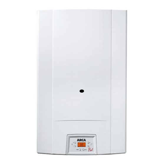
WALL HUNG BOILERS
INSTRUCTIONS MANUAL
To be used for
INSTALLATION, USE AND MAINTENANCE
PIXEL 25 N
PIXEL 25 NR
PIXEL 29 F
PIXEL 29 FR
PIXEL 25 F
PIXEL 25 FR
PIXEL IN 25 F
PIXEL IN 25 FR
PIXEL ES 25 F
PIXEL ES 25 FR
IMPORTANT
The first boiler ignition and the warranty have to be carried out by an authorised
personnel
LIB0900P – Rev. 1 - 21/02/2006 - 28 pagine
Advertisement
Table of Contents

Summarization of Contents
1. TECHNICAL DATA
1.1 Dimensions
Provides physical dimensions (length, height, depth, etc.) for different boiler models.
1.2 Hydraulic Scheme
Illustrates the internal water circulation system and lists key components.
1.3 Available Head
Graph showing the relationship between water flow rate and available head.
1.4 General layout of the main components of model PIXEL 25 N
Diagram showing the location of main components within the PIXEL 25 N model.
1.5 General layout of the main components of models: PIXEL 25 F, PIXEL ES 25 F, PIXEL IN 25 F
Diagram showing the location of main components for PIXEL 25 F, ES 25 F, IN 25 F models.
1.6 General layout of the main components of model PIXEL 29 F
Diagram showing the location of main components within the PIXEL 29 F model.
1.7 TECNICAL DATA
Comprehensive table detailing technical specifications for various models.
1.6 ELECTRICAL SCHEME of PIXEL 25 N
Wiring diagram for the PIXEL 25 N model, showing electrical connections.
1.7 ELECTRICAL SCHEME of PIXEL 25 NR
Wiring diagram for the PIXEL 25 NR model, detailing electrical connections.
1.8 ELECTRICAL SCHEME of PIXEL 25 F, PIXEL ES 25 F, PIXEL IN 25 F, PIXEL 29 F
Wiring diagram for PIXEL 25 F, ES 25 F, IN 25 F, and 29 F models.
1.8 ELECTRICAL SCHEME of PIXEL 25 FR, PIXEL ES 25 FR, PIXEL IN 25 FR, PIXEL 29 FR
Wiring diagram for PIXEL 25 FR, ES 25 FR, IN 25 FR, and 29 FR models.
2 INSTALLATION INSTRUCTIONS
2.1 DIFFERENT VENTING OPTIONS: PIXEL 25 F, PIXEL ES 25 F, PIXEL IN 25 F, PIXEL 29 F
Describes various methods for flue gas discharge and air intake.
2.1.2 LENGTH OF FLUE GAS DUCT: PIXEL 25 F, PIXEL ES 25 F, PIXEL IN 25 F
Specifies maximum allowed lengths for flue gas ducts for specific models.
2.1.3 LENGTH OF FLUE GAS DUCT: PIXEL 29 F
Specifies maximum allowed lengths for flue gas ducts for the PIXEL 29 F model.
2.2 COMBUSTION PRODUCT DISCHARGE: PIXEL 25 N
Details requirements for chimney connection and direct discharge for PIXEL 25 N.
2.3 BOILER PLACING
Instructions and guidelines for correctly positioning and mounting the boiler.
2.4 HYDRAULIC CONNECTIONS
Procedures and requirements for connecting the boiler's water circuits.
2.5 ELECTRIC CONNECTIONS
Guidelines for connecting the boiler to the electrical supply and external controls.
2.6 GAS CONNECTION
Instructions for safely connecting the boiler to the gas supply.
2.7 SETTING OF CONTROL PANEL
Explains how to use and configure the boiler's control interface.
2.8 ADJUSTMENT INSTRUCTIONS: NOMINAL HEAT AND MINIMUM HEAT
Details procedures for adjusting the boiler's heating output levels.
2.9 SLOW IGNITION AND NOMINAL HEAT ADJUSTMENT
Instructions for setting slow ignition and nominal heat parameters.
2.10 DIFFERENT GASES
Procedures for converting the boiler to operate on different types of gas.
2.11 INJECTORS PRESSURE TABLE: PIXEL 25 N
Table showing injector sizes and gas pressures for PIXEL 25 N.
2.12 INJECTORS PRESSURE TABLE: PIXEL 25 F, PIXEL ES 25 F, PIXEL IN 25 F
Table showing injector sizes and gas pressures for PIXEL 25 F, ES 25 F, IN 25 F.
2.13 INJECTORS PRESSURE TABLE: PIXEL 29 F
Table showing injector sizes and gas pressures for PIXEL 29 F.
3. MAINTENANCE INSTRUCTIONS
3.1 INTRODUCTION
General overview of maintenance procedures and requirements.
3.2 CIRCULATION DEBLOCKING
Steps to resolve issues with a blocked circulator pump.
4. USER'S INSTRUCTIONS
4.1 CONTROL PANEL
Explanation of the boiler's control panel buttons, indicators, and displays.
4.2 IGNITION
Steps for initiating the boiler's ignition sequence.
4.3 SUMMER MODE
How to configure the boiler for domestic hot water production only.
4.4 WINTER MODE
How to configure the boiler for both heating and domestic hot water.
4.5 BREAK DOWN SIGNALS
List of error codes and their corresponding descriptions.
4.6 TEMPORARILY TURNING BOILER OFF
Methods for switching the boiler off for short periods.
4.7 LONG TERM SHUT DOWN
Instructions for safely storing the boiler for extended periods.
4.8 SUGGESTIONS
General advice and recommendations for boiler operation and care.
4.9 FUNCTIONING PROBLEMS
Troubleshooting guide for common boiler issues and their causes/remedies.


Need help?
Do you have a question about the PIXEL 25 F and is the answer not in the manual?
Questions and answers