Summarization of Contents
LCD Specifications
Product Features
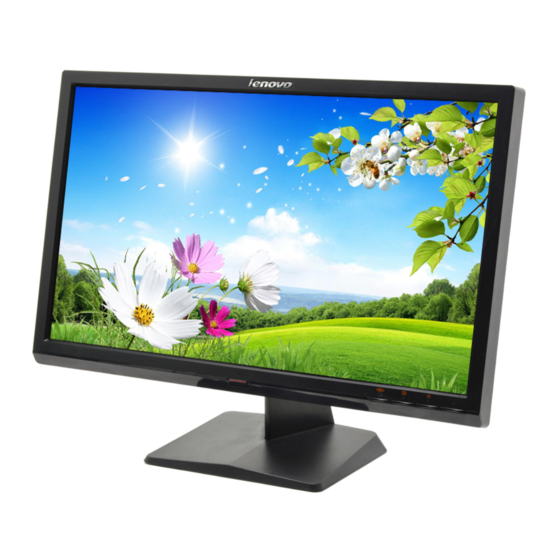
Detailed specifications for the Lenovo L2021 Wide monitor.
Factory Preset Modes
List of predefined display resolutions and their refresh rates.
Operation Instructions
Basic Connection
Instructions for connecting the monitor to a PC.
Control Buttons and OSD
Explanation of monitor control buttons and OSD functions.
OSD Menu Adjustment Steps
Step-by-step guide for navigating and adjusting the On-Screen Display menu.
Interface Description
VGA Interface Pinout
Pinout and description for the VGA connector.
DVI Interface Pinout
Pinout and description for the DVI connector.
Panel Features and Specifications
General Specifications
General technical specifications of the LCD panel.
Absolute Maximum Ratings
Electrical and environmental limits for the LCD panel.
Electrical Characteristics
Electrical characteristics of the TFT LCD module and backlight unit.
Panel Block Diagram and LVDS
Panel Block Diagram
Block diagram of the LCD panel and its components.
LVDS Connector Pin Assignment
Pin assignment details for the LVDS connector.
Block Diagrams
LCD Block Diagram
Block diagram of the LCD module components.
MainBoard Block Diagram
Block diagram of the main control board.
Power/Inverter Board Diagram
Block diagram of the power and inverter board.
Circuit Schematics
Main Board Schematic
Circuit schematic for the main board (715G3327-1).
Power Board Schematic
Circuit schematic for the power board (715G4174-2).
Inverter Part Schematic
Circuit schematic for the inverter part.
Key Board Schematic
Circuit schematic for the key board (715G3248/715G3249).
Explore Views
Exploded View Drawing
Exploded view diagram showing monitor components and part numbers.
PCB Layouts
MainBoard PCB Layout
PCB layout diagram for the main board (715G3327-1).
PowerBoard PCB Layout
PCB layout diagram for the power board (715G4174).
KeyBoard PCB Layout
PCB layout diagram for the key board.
Maintenance and Disassembly
Maintainability Requirements
List of required tools and equipment for maintenance.
Disassembly Procedure
Standard Operating Procedure for disassembling the monitor.
Stand Assembly Removal
Steps to remove the monitor stand assembly.
Back Cover and Board Removal
Steps to remove the monitor back cover and internal circuit boards.
Troubleshooting Guide
Main Board No Power
Troubleshooting steps for the main board when the monitor has no power.
No Picture (LED Orange)
Troubleshooting steps for no picture display with an orange LED.
White Screen Issue
Troubleshooting steps for a white screen display.
Power Board 5V/12V Issues
Troubleshooting steps for power issues on the power board.
Panel No Backlight
Troubleshooting steps for the panel backlight issue.
Software Update Procedures
Key Board OSD Troubleshooting
Troubleshooting steps for OSD issues related to the keyboard.
ISP Tool Connection Setup
Instructions for connecting the ISP tool and PC for software update.
Driver and RTD Tool Installation
Steps to install the necessary USB driver software and RTD Tool.
ISP Tool Configuration
Steps for selecting ISP tool, saving HDCP key, and selecting pages.
Software File Selection and Programming
Steps to select software files and initiate the programming process.
Automatic Identification and Size Selection
Steps for automatic identification and selecting "Externd True Size".
DDC Program Writing
DDC Program Setup and Execution
Steps for PC setup, connecting DDC device, installing drivers, and running the program.
Factory Mode Adjustment
Factory Mode Entry Procedure
Instructions to enter the monitor's factory mode and perform DDC re-writing.


Need help?
Do you have a question about the L2021 WA and is the answer not in the manual?
Questions and answers