Table of Contents
Advertisement
SERVICE MANUAL
(Except UK Model)
(UK Model only)
Refer to the SERVICE MANUAL of VHS
MECHANICAL ADJUSTMENT
MECHANICAL ADJUSTMENTS. (9-921-647-11)
The abbreviations of SE100/SE200/SE250/SE300/SE400/SE450/SX100/SX250 contained in this service manual
are indicated when these models are common to all their corresponding models as given below.
Abbreviated models name
SE100
All models name
SE100A1
SLV-
SE100A2
SE100K
System
C
hannel coverage
SLV-SE100K,SE400K,SE450K,SX100K:
PAL (B/G, D/K)
VHF E2–E12, R1–R12
UHF E21–E69, R21–R69
CATV S1–S41, S01–S05
SLV-SE200G/I, SE300G:
PAL (I)
VHF IA to IJ, SA10 to SA13 (SLV-SE200I only)
UHF B21 to B69
CATV S01 to S05, S1 to S20 (SLV-SE200I only)
HYPER S21 to S41 (SLV-SE200I only)
SLV-SE100A1/A2, SE200V1/V2, SE250D/P,
SE300D1/D2, SE450D/P, SX250D:
PAL (B/G)
VHF E2 to E12
Canaux VHF italiens A to H
UHF E21 to E69
CATV S01 to S05, S1 to S20
HYPER S21 to S41
SLV-SE100/SE200/SE250/SE300/
SE400/SE450/SX100/SX250
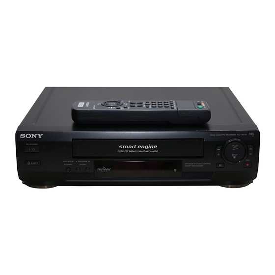
Photo : SLV-SE450D
RMT-V257B
for
SE200
SE250
SE300
SE400
SE200G
SE250B
SE300D1
SE400K
SE200I
SE250D
SE300D2
SE200V1
SE250P
SE300G
SE200V2
SPECIFICATIONS
SLV-SE250B,SE450B:
SECAM (L):
VHF F2 to F10
UHF F21 to F69
CATV B to Q
HYPER S21 to S41
PAL (B/G):
VHF E2 to E12
Canaux VHF italiens A to H
UHF E21 to E69
CATV S01 to S05, S1 to S20
HYPER S21 to S41
RF output signal
UHF channels 21–69
Aerial out
75-ohm asymmetrical aerial socket
RMT-V257/V257A/V257B/V257C/V287
SLV-SE100A1/A2/K,SE200V1/V2,
East European Model
SE450
SX100
SX250
SE450B
SX100K
SX250D
SE450D
SE450K
SE450P
Tape speed
SP:
PAL/MESECAM 23.39 mm/s
NTSC 33.35 mm/s
(SLV-SE250B,SE450B only)
SECAM 23,39 mm/s (recording/playback)
M
LP*:
PAL/MESECAM 11.70 mm/s
(playback only, except: SLV-SE200G/I, SE300G)
(recording/playback: SLV-SE200G/I, SE300G)
NTSC 16.67 mm/s (playback only)
(SLV-SE450B only)
SECAM 11,70 mm/s (recording/playback)
M
EP*:
NTSC 11.12 mm/s (playback only)
(SLV-SE200G/I, SE250D/P, SE300D1/D2/G,
SE450B/D/P, SX250D)
Maximum recording/playback time
10 hrs. in LP mode (with E300 tape)
Fast-forward and rewind time
Approx. 3 min. (with E180 tape)
VIDEO CASSETTE RECORDER
AEP Model
SE250B/D/P,SE300D1/D2,
SE400K,SE450B/D/K/P,
SX100K,SX250D
UK Model
SLV-SE200G/I,SE300G
Russian Model
SLV-SE100K,SE400K,
SE450K,SX100K
S MECHANISM
ESECAM 23,39 mm/s (playback only)
ESECAM 11,70 mm/s (playback only)
— Continued on next page —
Advertisement
Table of Contents

Related Manuals for Sony SLV-SE100


Summarization of Contents
VCR Specifications and Features
System Specifications
Details channel coverage and RF output signal for various VCR models.
Tape Speed Standards
Specifies tape speeds (SP, LP, EP) and recording/playback times.
Safety Check-Out Procedures
Post-Repair Safety Checks
Essential safety checks to perform after service.
Error Code Identification
VCR Error Code Reference
Lists error codes and corresponding malfunctions for the VCR.
VCR Mode Code Reference
Lists mode codes indicating the VCR's operational state.
SECTION 1 GENERAL
Getting Started and Basic Setup
Initial setup steps including unpacking and remote commander configuration.
Basic VCR Operations
Core functions like playing tapes and recording TV programs.
Additional VCR Operations
Advanced functions like searching, timer settings, and picture adjustment.
Editing with Another VCR
Procedure for connecting and editing tapes with an external VCR.
SECTION 2 DISASSEMBLY
Front Panel and Case Assembly
Steps for disassembling the front panel and upper case.
Internal Views and Board Locations
Identification of internal components and circuit board locations.
SECTION 3 BLOCK DIAGRAMS
Overall System Block Diagram
High-level overview of VCR system interconnections.
Detailed Signal Path Diagrams
Schematic diagrams for Video, Audio, Servo, and Power blocks.
SECTION 4 PRINTED WIRING BOARDS AND SCHEMATIC DIAGRAMS
MA-372 Board Schematics
Detailed circuit diagrams for the main MA-372 board.
Auxiliary Board Diagrams
Printed wiring boards for JK-179, KK-22, and Power Supply.
SECTION 5 INTERFACE, IC PIN FUNCTION DESCRIPTION
System Control IC Pin Functions
Pin assignments for system control ICs on the MA-372 board.
Microprocessor and Mode Control Pins
Detailed pin functions for the main microprocessor and mode controls.
SECTION 6 ADJUSTMENTS
Mechanical Adjustments Reference
Reference information for mechanical adjustments.
Electrical Adjustment Procedures
Preparation, setup, and connection guidelines for electrical adjustments.
System and Power Supply Checks
Procedures for checking power supply voltages and system functions.
SECTION 7 REPAIR PARTS LIST
Exploded Views of Components
Visual breakdown of VCR parts for identification.
Electrical Parts Details
Comprehensive list of electrical components with part numbers.
POWER BLOCK
Power Block Components
List of capacitors, resistors, transistors, and ICs in the power block.
Included Accessories and Hardware
List of supplied accessories and hardware items.
Need help?
Do you have a question about the SLV-SE100 and is the answer not in the manual?
Questions and answers