Table of Contents
Advertisement
DVP-NS15/NS51P/NS43P/NS53P/K56P
SERVICE MANUAL
RMT-D175P
RMT-D175A
Notes: Australia/NZ model only
This manual have
three different type
of DVD player
appearance/structure .
Please take note.
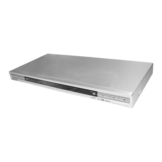
Photo : DVP-NS15
Photo : DVP-NS51P
Photo : DVP-K56P
Photo : DVP-NS43P/NS53P
/RMT-D175C/RMT-D175P
RMT-D175A
Australian/New Zealand Model
IND,PAK,MAR Model
CD/DVD PLAYER
AEP Model
UK Model
DVP-NS15
Chinese Model
DVP-NS51P
Argentina Model
Brazilian Model
DVP-NS43P/NS53P
Singapore Model
Saudi Arabia Model
DVP-NS51P/K56P
Mexican Model
E Model
DVP-NS53P
Russian Model
DVP-K56P
Taiwan Model
DVP-K56P/NS51P
India Model
Iran Model
Middle East Model
Korean Model
Malaysian Model
Hong Kong Model
Vietnam Model
DVP-NS51P
Advertisement
Table of Contents

Summarization of Contents
Section 1 General
General Precautions and Safety Guidelines
Covers essential safety, handling, and operational precautions for the unit.
Disc Compatibility and Notes
Lists compatible disc types and important notes regarding disc playback.
Hooking Up the Player
Step-by-step guide on connecting the DVD player to other components.
Playing Discs and Menus
Explains disc playback, DVD menus, and various play modes.
Searching and Playback Features
Covers scene searching, picture navigation, and information display.
Sound and Movie Playback Adjustments
Details sound settings, virtual surround, angle/subtitle changes, and picture adjustments.
MP3 and JPEG File Playback
Guides on playing MP3 audio tracks and JPEG image files, including slideshows.
Additional Functions and Settings
Explains disc locking, TV control, and system settings for customization.
Section 2 Disassembly
Upper Case Disassembly
Procedure for removing the upper case of the unit.
Front Panel and Board Removal
Steps for disassembling the front panel, switch board, and MC board.
Loading Assembly Disassembly
Instructions for removing the loading assembly mechanism.
Optical Pick-Up Removal
Guidance on removing the optical pick-up device.
Rear Panel and Board Access
Procedures for accessing the rear panel, MV board, and IF board.
Switching Regulator and Internal Views
Details on switching regulator and internal component views.
Circuit Board Locations
Diagrams showing the locations of various circuit boards within the unit.
Section 3 Block Diagrams
Overall System Block Diagram
Provides a comprehensive overview of the player's internal system architecture.
Power Line Block Diagram
Illustrates the power distribution and regulation within the device.
System Control and Signal Processor Block Diagrams
Details the system control and signal processing pathways.
RF/Servo and Video Block Diagrams
Shows the RF signal processing, servo control, and video signal flow.
Audio and Interface Control Block Diagrams
Outlines the audio signal processing and interface control logic.
Section 4 Printed Wiring Boards and Schematic Diagrams
Frame Schematic Diagram
Overall schematic diagram showing the main frame connections.
Waveforms Analysis
Displays key waveforms for MV-48 and MV-47 boards for analysis.
IF Board PWBs and Schematics
PWBs and schematics for IF-143, IF-144, and IF-145 interface boards.
MC-161 Board (PWB and Schematic)
Printed wiring board and schematic for the MC-161 MIC-ECHO board.
MS-203 Board (PWB and Schematic)
Printed wiring board layout and schematic for the MS-203 loading motor board.
MV-47 Board (PWB and Schematics)
Printed wiring boards and schematic diagrams for the MV-47 board.
MV-48 Board (PWB and Schematics)
Printed wiring boards and schematic diagrams for the MV-48 board.
Switch Board PWBs
Printed wiring board layouts for SW-467, SW-468, SW-469, and SW-475 boards.
Power Block PWBs and Schematics
PWBs and schematic diagrams for the power supply units.
Section 5 IC Pin Function Description
System Control Pin Function (MV-47/48 Boards IC101)
Detailed pin functions for the system control IC on MV-47/48 boards.
Section 6 Test Mode
Executing IOP Measurement
Procedure for measuring IOP (Input/Output Port) values.
Emergency History Check
How to check and interpret the player's emergency history log.
Initializing Setup Data
Steps to reset all player settings to their default values.
IF CON Self Diagnostic Function
Details on self-diagnostic tests for interface boards and mode operations.
Self Check Mode Operation and Display
Details operations and displays within the Self Check mode.
Section 7 Electrical Adjustment
Power Supply Output Voltage Check
Procedure to verify the output voltages of the power supply unit.
Adjustment of Video System (DVP-NS15)
Video output level adjustments for the DVP-NS15 model.
Adjustment of Video System (Except DVP-NS15)
Video output level adjustments for models other than DVP-NS15.
Section 8 Repair Parts List
Exploded Views of Main Section
Visual breakdown of the main assembly for parts identification.
Exploded View of Mechanism Deck Assembly
Visual breakdown of the mechanism deck for parts identification.
Electrical Parts List
Comprehensive list of electrical components and their part numbers.


Need help?
Do you have a question about the DVP-NS51P and is the answer not in the manual?
Questions and answers