Table of Contents
Advertisement
HISTORY INFORMATION FOR THE FOLLOWING MANUAL:
SERVICE MANUAL
MODEL NAME
KV-29FA350
KV-29FA350
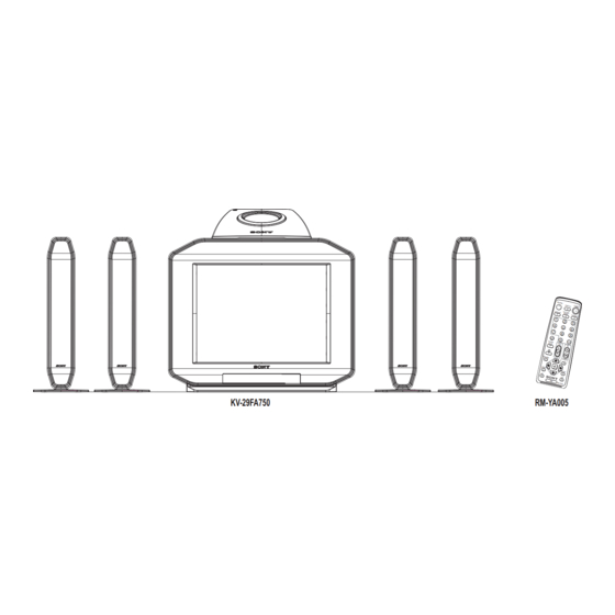
KV-29FA750
KV-29FA750
ORIGINAL MANUAL ISSUE DATE: 2/2007
REVISION DATE
2/2007
9-883-734-01
REMOTE COMMANDER
RM-YA005
LATIN NORTH
RM-YA005
LATIN SOUTH
RM-YA005
LATIN NORTH
RM-YA005
LATIN SOUTH
SUBJECT
No revisions or updates are applicable at this time.
BX-1L
DESTINATION
CHASSIS NO.
SCC-S79P-A
SCC-S79Q-A
SCC-S79R-A
SCC-S79S-A
®
TRINITRON
COLOR TELEVISION
CHASSIS
Advertisement
Chapters
Table of Contents

Summarization of Contents
SELF-DIAGNOSTIC FUNCTION
Diagnostic Test Indicators
Describes error codes, probable causes, and detected symptoms for TV malfunctions.
Display of STANDBY LED Flash Count
Explains the meaning of the STANDBY LED flash counts for diagnostic purposes.
SECTION 1: DISASSEMBLY
1-1. REAR COVER REMOVAL
Step-by-step procedure for removing the rear cover of the TV unit.
1-2. CHASSIS ASSEMBLY REMOVAL
Procedure for safely removing the main chassis assembly from the TV.
1-3. SERVICE POSITION
Describes the correct orientation of the TV for performing service operations.
1-4. PICTURE TUBE REMOVAL
Detailed instructions for safely removing the picture tube, including warnings.
ANODE CAP REMOVAL PROCEDURE
Specific steps and warnings for safely removing the picture tube's anode cap.
HOW TO HANDLE AN ANODE CAP
Guidelines for safe and proper handling of the picture tube anode cap.
SECTION 2: SET-UP ADJUSTMENTS
2-1. BEAM LANDING
Instructions for adjusting the electron beam landing on the CRT screen.
2-2. CONVERGENCE
Procedures for aligning the RGB electron beams for accurate color display.
Vertical Static Convergence
Specific adjustment for vertical static convergence of color beams.
Horizontal Static Convergence
Specific adjustment for horizontal static convergence of color beams.
Y Separation Axix Correction Magnet Adjustment
Adjusting the Y separation axis correction magnet for image alignment.
2-3. FOCUS ADJUSTMENT
Steps to achieve a sharp and clear focus for the picture.
Screen Corner Convergence
Fine-tuning convergence adjustments at the screen corners.
2-4. SCREEN (G2)
Procedure for adjusting the screen grid voltage (G2) for optimal brightness.
SECTION 3: CIRCUIT ADJUSTMENTS
3-1. REMOTE ADJUSTMENT BUTTONS AND INDICATORS
Explains the function of remote control buttons used for service adjustments.
3-2. ACCESSING THE SERVICE MENU
Guide on how to enter the TV's hidden service menu for adjustments.
3-3. CONFIRMING SERVICE ADJUSTMENT CHANGES
Steps to verify that service adjustments have been correctly applied.
3-4. WHITE BALANCE ADJUSTMENTS
Procedure for calibrating the white balance for accurate color reproduction.
3-5. PICTURE QUALITY ADJUSTMENTS
Various adjustments to optimize overall picture quality and performance.
Sub Color Adjustment
Fine-tuning color saturation and hue for specific color ranges.
Sub Hue Adjustment
Adjusting the color tint to correct color balance.
Sub Bright Adjustment
Fine-tuning the brightness levels for optimal picture appearance.
Geometry Adjustment
H-Trapezoid Adjustment
Correcting horizontal trapezoidal distortion in the picture display.
Normal Mode 50Hz/60Hz
Geometry adjustment settings for standard TV modes.
Wide Mode
Geometry adjustment settings for wide screen viewing modes.
3-6. SERVICE DATA
Table of default service parameters and initial values for adjustments.
SECTION 4: DIAGRAMS
4-1. CIRCUIT BOARDS LOCATION
Visual guide identifying the location of major circuit boards within the TV.
4-2. PRINTED WIRING BOARD AND SCHEMATIC DIAGRAM INFORMATION
Explains diagram symbols, conventions, and component identification.
4-3. BLOCK DIAGRAM
Simplified diagram illustrating the TV's functional blocks and signal flow.
4-4. SCHEMATICS AND SUPPORTING INFORMATION
Detailed electronic circuit schematics for various TV boards.
CV BOARD SCHEMATIC DIAGRAM
Detailed schematic diagram for the CV board.
H2 BOARD SCHEMATIC DIAGRAM
Detailed schematic diagram for the H2 board.
J4 BOARD SCHEMATIC DIAGRAM
Schematic diagram for the J4 board.
K2 BOARD SCHEMATIC DIAGRAM (1 OF 2)
First part of the detailed schematic for the K2 board.
K2 BOARD SCHEMATIC DIAGRAM (2 OF 2)
Second part of the detailed schematic for the K2 board.
SECTION 5: EXPLODED VIEWS
5-1. CHASSIS
Exploded view diagram of the TV chassis with numbered parts.
5-2. PICTURE TUBE
Exploded view diagram of the picture tube assembly and its components.


Need help?
Do you have a question about the KV-29FA750 and is the answer not in the manual?
Questions and answers