Sony STR-DB1080 - Fm Stereo/fm-am Receiver Service Manual
Hide thumbs
Also See for STR-DB1080 - Fm Stereo/fm-am Receiver:
- Operating instructions manual (72 pages) ,
- Limited warranty (1 page)
Table of Contents
Advertisement
STR-DA2ES/DB1080
SERVICE MANUAL
Ver 1.1 2003.07
This receiver incorporates Dolby* Digital and Pro Logic Surround
and the DTS** Digital Surround System.
* Manufactured under license from Dolby Laboratories.
"Dolby", "Pro Logic" and the double-D symbol are
trademarks of Dolby Laboratories.
** "DTS", "DTS-ES Extended Surround" and "Neo:6" are
trademarks of Digital Theater Systems, Inc.
AUDIO POWER SPECIFICATIONS
POWER OUTPUT AND TOTAL
HARMONIC DISTORTION:
(Models of area code U only)
With 8 ohm loads, both channels driven, from
20 – 20,000 Hz; rated 100 watts per channel
minimum RMS power, with no more than
0.09 % total harmonic distortion from
250 milliwatts to rated output.
Amplifier section
POWER OUTPUT
Models of area code U, CA
Rated Power Output at Stereo Mode
(8 ohms 20 Hz – 20 kHz, THD 0.09 %)
100 W + 100 W
(4 ohms 20 Hz – 20 kHz, THD 0.09 %)
80 W + 80 W
Reference Power Output
(8 ohms 20 Hz – 20 kHz, THD 0.09 %)
FRONT
1)
:100 W + 100 W
CENTER
1)
: 100 W
1)
SURR
: 100 W + 100 W
SURR BACK
(4 ohms 20 Hz – 20 kHz, THD 0.09 %)
FRONT:
1)
80 W + 80 W
CENTER
1)
: 80 W
1)
SURR
: 80 W + 80 W
SURR BACK
Sony Corporation
9-874-061-02
2003G05-1
Home Audio Company
C 2003.07
Published by Sony Engineering Corporation
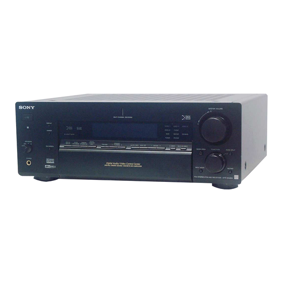
Photo: STR-DA2ES
SPECIFICATIONS
Models of other area code
Rated Power Output at Stereo Mode
(8 ohms 1 kHz, THD 0.7 %)
(4 ohms 1 kHz, THD 0.7 %)
Reference Power Output
(8 ohms 1 kHz, THD 0.7 %)
(4 ohms 1 kHz, THD 0.7 %)
(8 ohms 20 Hz – 20 kHz, THD 0.09 %)
(4 ohms 20 Hz – 20 kHz, THD 0.09 %)
1)
: 100 W
1) Depending on the sound field settings and the
source, there may be no sound output.
1)
: 80 W
2) Measured under the following conditions:
Area code
100 W + 100 W
2)
E
SP, CEL, CEK, KR
90 W + 90 W
2)
2)
Frequency response
PHONO
1)
FRONT
: 100 W + 100 W
CENTER
1)
: 100 W
1)
SURR
: 100 W + 100 W
CD/SACD, TAPE,
1)
SURR BACK
: 100 W
MD/DAT, TV/SAT,
DVD/LD, VIDEO 1, 2,
1)
FRONT
: 90 W + 90 W
3
CENTER
1)
: 90 W
SURR
1)
: 90 W + 90 W
1)
SURR BACK
: 90 W
Inputs (Analog)
PHONO
FRONT
1)
: 90 W + 90 W
1)
CENTER
: 90 W
SURR
1)
: 90 W + 90 W
SURR BACK
1)
: 90 W
MULTI CH IN 1, 2,
CD/SACD, TAPE,
FRONT
1)
: 80 W + 80 W
MD/DAT, DVD/LD,
CENTER
1)
: 80 W
TV/SAT, VIDEO 1, 2,
SURR
1)
: 80 W + 80 W
3
SURR BACK
1)
: 80 W
3) INPUT SHORT.
4) Weighted network, input level.
FM STEREO FM-AM RECEIVER
US Model
Canadian Model
STR-DA2ES
AEP Model
UK Model
E Model
STR-DB1080
Power requirements
240 V AC, 50 Hz
230 V AC, 50 Hz
RIAA equalization curve
±0.5 dB
10 Hz – 100 kHz
+0.5/–2 dB (when
ANALOG DIRECT is
selected)
Sensitivity: 2.5 mV
Impedance: 50 kilohms
3)
S/N
: 86 dB (A, 2.5 mV
Sensitivity: 150 mV
Impedance: 50 kilohms
3)
S/N
: 96 dB
4)
(A, 150 mV
)
– Continued on next page –
4)
)
Advertisement
Table of Contents

Related Manuals for Sony STR-DB1080 - Fm Stereo/fm-am Receiver


Summarization of Contents
Service Manual and Specifications
Audio Power Specifications
Details audio output power and distortion across different channels and loads.
Model Specifications by Area Code
Lists power requirements and frequency response for various regional models.
Detailed Specifications
Input/Output, Tuner, and General Specifications
Covers I/O, tuner parameters, power requirements, and general unit specifications.
Safety and Component Handling
Safety Check-out and Leakage Test
Procedures for checking AC leakage and ensuring safety before unit release.
Safety-Related Component Warning
Warning about critical safety components and replacement guidelines.
Servicing Information
Servicing Notes and Model Identification
General notes, servicing precautions, and model identification details.
General Information
Location of Controls - Front Panel
Identifies and labels all controls and indicators on the front panel.
Disassembly Procedures
Disassembly Flow
Outlines the step-by-step process for disassembling the unit.
Test Modes
Test Mode Procedures
Instructions for activating various test modes for troubleshooting and diagnostics.
Electrical Adjustments
OSD Adjustment Procedures
Details the steps for adjusting OSD (On-Screen Display) parameters.
Diagrams and Schematics
Block Diagrams Overview
Provides block diagrams for various sections of the unit.
Schematic Diagram Notes and Board Locations
Explains symbols, notations, and board layouts for schematic diagrams.
Exploded Views
Case, Front Panel, and Chassis Exploded Views
Illustrates the assembly of the unit's case, front panel, and chassis.
Board Sections Exploded Views
Details the assembly of the bias, main, and foot sections.
Electrical Parts List
Major Board Components (Capacitors, Resistors, ICs)
Comprehensive list of components for AC BIAS, DC, DIGITAL, and MAIN boards.
Accessories and Miscellaneous Parts
Lists accessories, miscellaneous parts, and regional manual part numbers.
Need help?
Do you have a question about the STR-DB1080 - Fm Stereo/fm-am Receiver and is the answer not in the manual?
Questions and answers