Sign In
Upload
Download
Table of Contents
Contents
Add to my manuals
Delete from my manuals
Share
URL of this page:
HTML Link:
Bookmark this page
Add
Manual will be automatically added to "My Manuals"
Print this page
×
Bookmark added
×
Added to my manuals
Manuals
Brands
Kubota Manuals
Engine
V1903-B
Workshop manual
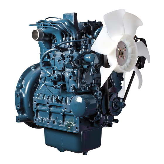
Kubota V1903-B Workshop Manual
92.4mm stroke series
Hide thumbs
1
2
3
4
5
6
7
8
9
10
11
12
13
14
15
16
17
18
19
20
21
22
23
24
25
26
27
28
29
30
31
32
33
34
35
36
37
38
39
40
41
42
43
44
45
46
47
48
49
50
51
52
53
54
55
56
57
58
59
60
61
62
63
64
65
66
67
68
69
70
71
72
73
74
75
76
77
78
79
80
81
82
83
84
85
86
87
88
89
90
91
92
93
94
95
96
97
98
99
100
101
102
103
104
105
106
107
108
109
110
111
112
113
114
115
116
117
118
119
120
121
122
123
124
125
126
127
128
129
130
131
132
133
134
135
136
137
138
139
140
141
142
143
144
145
146
147
148
149
150
151
152
153
154
155
156
157
158
159
160
161
162
163
164
165
166
167
168
169
170
171
172
173
174
175
176
177
178
179
180
181
182
183
184
185
186
187
188
189
190
191
192
193
194
195
196
197
198
199
200
201
202
203
204
205
206
207
208
209
210
211
212
213
214
215
216
Table Of Contents
217
page
of
217
Go
/
217
Contents
Table of Contents
Troubleshooting
Bookmarks
Table of Contents
Contents
Safety Starting
Safety Working
Ventilate Work Area
Prevent Acid Burns
Dispose of Fluid Properly
Prepare for Emergencies
Specifications
Performance Curves
Dimensions
Mechanism
Feature
Engine Body
Cylinder Block
Cylinder Head
Crankshaft
Piston and Piston Rings
Connecting Rod
Camshaft
Flywheel
Rocker Arm
Lubricating System
General
Engine Oil Flow
Oil Pump
Relief Valve
Oil Filter Cartridge
Oil Pressure Switch
Cooling System
Water Pump
Thermostat
Radiator
Radiator Cap
Intake and Exhaust System
Air Cleaner
Muffler
Fuel System
Injection Pump
Pump Element
Delivery Valve
Reverse Flow Preventing Function
Suck-Back Function
Dumping Valve
Injection Control
At Fuel Injection
At Suck-Back
Injection Nozzle
Fuel Filter
Fuel Lift Pump
Governor
At Idling
At High Speed Running with Overload
To Stop Engine
Electrical System
Charging System
Alternator
Regulator
Disassembling and Servicing
Engine Identification
Model Name and Engine Serial Number
Cylinder Number
General Precaution
Tightening Torques
Troubleshooting
Servicing Specifications
Maintenance Check List
Check and Maintenance
Daily Check Points
Checking Engine Oil Level
Checking and Replenish Cooling Water
Check Point of Every 50 Hours
Checking Fuel Pipe
Changing Engine Oil
Checking Fan Belt Tension
Checking Fan Belt Damage
Cleaning Air Cleaner
Changing Engine Oil Filter Cartridge
Changing Fuel Filter Cartridge
Check Point of Every 800 Hours
Checking Valve Clearance
Special Tools
Flywheel Puller
Special-Use Puller Set
Valve Seat Cutter Set
Diesel Engine Compression Tester
Oil Pressure Tester
Auxiliary Socket for Fixing Crankshaft Sleeve
Plastigage
Red Check (Crack Check Liquid)
Injection Pump Pressure Tester
Valve Guide Replacing Tool
Idle Gear Bushing Replacing Tool
Small End Bushing Replacing
Crankshaft Bearing 1 Replacing
Flywheel Stopper
Compression Pressure
Top Clearance
Draining Water and Oil
External Components
Air Cleaner, Muffler and Others
Cylinder Head and Valves
Cylinder Head Cover and Nozzle Holder
Nozzle Heat Seal Service Removal Procedure
Rocker Arm, Push Rod and Injex. Manifold
Cylinder Head and Tappet
Valve
Fuel Feed Pump and Pump Cover
Governor Spring
Speed Control Plate
Start Spring
Gear Case
Crankshaft Oil Slinaer
Idle Gear and Camshaft
Fuel Camshaft and Fork Lever Assembly
Oil Pump and Crank Gear
Piston and Connecting Rod
Oil Fan and Oil Strainer
Piston Ring and Connecting Rod
Bearina Case Cover and Crankshaft
Servicing
Main Bearing Case Assembly
Cylinder Head Surface Flatness
Cylinder Head Flaw
Valve Recessing
Clearance between Valve Stem and Guide
Correcting Valve and Valve Seat
Valve Spring
Oil Clearance of Rocker Arm Shaft and Bearing
Timing Gear Anr Camshaft
Timing Gear Backlash
End Play of Camshaft
Camshaft Alignment
Oil Clearance of Camshaft Journal
Clearance between Idle Gear Shaft and Idle Gear Bushing
Replacing Idle Gear Bushing
Piston Pin-Bore I.D.
Oil Clearance between Piston Pin and Small End Bushing
Replacing Connecting Rod Small End Bushing
Piston Ring Gap
Clearance between Piston Ring and Groove
Connecting Rod Alignment
Side Clearance of Crankshaft
Crankshaft Alignment
Oil Clearance between Crank Pin and Crank Pin Bearing
Crankshaft Sleeve Wear
Replacing Crankshaft Sleeve
Oil Clearance between Crankshaft Journal and Crankshaft Bearing
Undersized and Oversized Bearing
Cylinder Bore
Cylinder Bore I.D.
Correcting Cylinder
Engine Oil Pressure
Rotor and Lobe Clearance
Clearance between Rotor and Cover
Fan Belt Tension
Thermostat's Valve Opening Temperature
Radiator Water Leakage
Radiator Cap Air Leakage
Injection Timing
Fuel Tightness of Pump Element
Fuel Tightness of Delivery Valve
Nozzle Injection Pressure
Fuel Tightness of Needle Valve Seat
Nozzle Holder
Motor Test
Magnet Switch
Glow Plug
Output Current
Connect Voltage
No-Load Testing
Rotor Coil Resistance
Cut-In Voltage
No-Load Regulating Voltage
Regulator Relay
Compact Type
Regulating Voltage
No-Load Characteristics
Starter Motor
Brush Holder
Housing, Idle Gear and Overrunning Clutch
Plunger
Pulley
Drive Side End Frame and Rotor
Rectifier
Rear End Cover
IC Regulator
Rear End Frame
Rotor
Retainer Plate
Bearing on the Drive End Side
Bearing at the Slip Ring Side
Armature Coil
Yoke
Armature Bearing
Overrunning Clutch
Slip Ring
Brush Wear
Rotor Coil
Stator Coil
Positive Diodes
Negative Diodes
N Terminal and Coil Connection
Advertisement
Quick Links
1
Specifications
2
Cylinder Head
Download this manual
WORKSHOP MANUAL
DIESEL ENGINE
MANUEL DNTELIER
MOTEUR DIESEL
WERKSTAT TANLEITUNG
DIESELMOTOR
92.4mm STROKE SERIES
MOTEUR DE 92.4mm DE COURSE
SERIENMOTOR
~
MIT 92.4mm HUB
~
~~
~
Table of
Contents
Previous
Page
Next
Page
1
2
3
4
5
Advertisement
Table of Contents
Need help?
Do you have a question about the V1903-B and is the answer not in the manual?
Ask a question
Questions and answers
Related Manuals for Kubota V1903-B
Engine Kubota D1005-E3BG Operator's Manual
(41 pages)
Engine Kubota Z482-E3 Operator's Manual
(74 pages)
Engine Kubota WSM 05-E3B Series Workshop Manual
(130 pages)
Engine Kubota D1005-E4BG Operator's Manual
(40 pages)
Engine Kubota D905-EBG Operator's Manual
(28 pages)
Engine Kubota D1005-E Operator's Manual
(90 pages)
Engine Kubota D1403-B Workshop Manual
92.4mm stroke series (217 pages)
Engine Kubota D1005-E3 Operator's Manual
(41 pages)
Engine Kubota 05 series Workshop Manual
(278 pages)
Engine Kubota 05 Series Workshop Manual
05 series (125 pages)
Engine Kubota BG Series Workshop Manual
(170 pages)
Engine Kubota V1502-B Workshop Manual
(110 pages)
Engine Kubota V1702-B Workshop Manual
(110 pages)
Engine Kubota V1902-B Workshop Manual
(110 pages)
Engine Kubota V1505-CR-TE5 Operator's Manual
(64 pages)
Engine Kubota WSM 05-E4B Series Workshop Manual
(168 pages)
Summarization of Contents
TO THE READER
Manual Structure Overview
Outlines the manual's division into "Mechanism" and "Disassembling and Servicing".
Safety First and General Precautions
Safety Symbol Definitions
Explains hazard symbols (Danger, Warning, Caution) and important notes.
Pre-Service Procedures
Lists essential steps to take before starting maintenance or repair work.
Safe Operation Practices
Covers safe starting, working, fire prevention, and ventilation.
Fluid Handling and Emergency Preparedness
Details proper fluid disposal, acid burn prevention, and emergency preparedness.
Engine Specifications and Data
Technical Specifications and Dimensions
Lists detailed technical data, power ratings, and dimensions for engine models.
Performance Curves
Displays engine performance curves based on SAE and DIN standards for various models.
Mechanism Overview
Engine Body Components
Details the cylinder block, head, crankshaft, pistons, connecting rods, etc.
Lubricating System Components
Explains the oil pump, filter, relief valve, and oil pressure switch.
Cooling System Components
Describes the radiator, water pump, thermostat, and fan belt.
Fuel System Components
Covers the fuel tank, filter, injection pump, nozzles, and lift pump.
Electrical System Components
Details the alternator, regulator, starter, and glow plugs.
Disassembling and Servicing
General Precautions and Identification
Covers engine identification and general safety precautions for disassembly.
Tightening Torque Specifications
Lists critical torque values for various fasteners to ensure assembly accuracy.
Troubleshooting Common Issues
Provides a diagnostic guide for common engine problems and their solutions.
Servicing Specifications - Key Components
Details specifications for cylinder head, valves, rocker arms, and camshafts.
Table of Contents
Save PDF
Print
Rename the bookmark
Delete bookmark?
Delete from my manuals?
Login
Sign In
OR
Sign in with Facebook
Sign in with Google
Upload manual
Upload from disk
Upload from URL
Need help?
Do you have a question about the V1903-B and is the answer not in the manual?
Questions and answers