Table of Contents
Advertisement
Quick Links
Advertisement
Table of Contents

Related Manuals for Atlas 215x


Summarization of Contents
SECTION 1 GENERAL INFORMATION
1-1. INTRODUCTION
Introduction to the Atlas 210x/215x transceiver and its capabilities.
GENERAL SPECIFICATIONS
Detailed specifications of the transceiver's features, design, and performance.
RECEIVER SPECIFICATIONS
Technical specifications for the receiver section, including sensitivity and selectivity.
TRANSMITTER SPECIFICATIONS
Technical specifications for the transmitter section, including power output and emissions.
MODEL 220-CS POWER SUPPLY CONSOLE SPECIFICATIONS
Specifications for the optional 220-CS power supply console.
MODEL 200-PS PORTABLE AC SUPPLY
Specifications for the optional 200-PS portable AC supply.
RECHARGEABLE BATTERY PACK
Information on the optional rechargeable battery pack for mobile operation.
SECTION 2 INSTALLATION
2-1. INTRODUCTION
Introduction to installation procedures for mobile, portable, and fixed stations.
2-2. GENERAL INFORMATION
General information pertaining to installation, including power requirements.
2-3. D.C. POWER.
Details on DC power sources and connections for the transceiver.
2-4. AUTOMOTIVE D.C. ELECTRICAL SYSTEMS.
Precautions and checks for automotive DC systems to protect the transceiver.
2-5. DELUXE MOUNTING KIT (DMK).
Information on the Deluxe Mobile Mounting Kit for transceiver installation.
2-6. D.C. CABLE (DCC).
Details on the DC Cable with polarity and overload protection.
2-7. CIGARETTE LIGHTER CABLE (CLC).
Information on using the Cigarette Lighter Cable for DC power.
2-8. PORTABLE BATTERY PACK.
Details on the portable battery pack for 12V DC power.
2-9. 220-CS AC CONSOLE.
Information on the 220-CS AC Console for powering the transceiver.
2-10. 200-PS PORTABLE AC SUPPLY.
Details on the 200-PS Portable AC Supply for power.
2-11. TRANSMISSION LINE IMPEDANCE MATCHING.
Importance of impedance matching for solid-state transmitters and SWR effects.
2-13. INFINITE SWR PROTECTION.
Description of the built-in SWR protection circuit.
2-14. SWR MEASUREMENTS.
Procedure for measuring Standing Wave Ratio (SWR).
2-15. MICROPHONE CONNECTIONS.
Guidelines for connecting microphones, including types and plug details.
2-17. CW KEY.
Instructions for connecting a CW key to the transceiver.
2-18. REMOTE CW TRANSMIT SWITCH FOR ATLAS TRANSCEIVERS.
Description and diagram for a remote CW transmit switch.
2-21. LINEAR AMPLIFIER CONNECTIONS.
How to connect a linear amplifier and ALC control.
2-23. DELUXE PLUG-IN MOBILE MOUNTING KIT.
Detailed instructions for installing the Deluxe Plug-in Mobile Mounting Kit.
2-24. MOBILE BRACKET KIT (MBK).
Instructions for installing the Mobile Bracket Kit.
2-25. INSTALLING D.C. POWER CABLE.
Procedure for installing the DC power cable, including battery connections.
2-27. OTHER D.C. INSTALLATIONS.
Alternative DC installation methods and polarity caution.
2-28. FIXED STATION INSTALLATIONS
Instructions for fixed station installations using the 220-CS console.
2-30. MOBILE ANTENNAS.
Considerations for mobile antennas and impedance matching.
2-31. CAPACITYMATCHINGMETHOD.
Method for impedance matching mobile antennas using capacitors.
2-33. FIXED STATION ANTENNAS
Guidance on fixed station antennas for various bands and matching.
2-34. ANTENNA TUNER OR. "MATCH BOX."
Usefulness of antenna tuners for compensating mismatches.
SECTION 3 OPERATION
3-1. INTRODUCTION
Introduction to operating the Atlas transceiver and its controls.
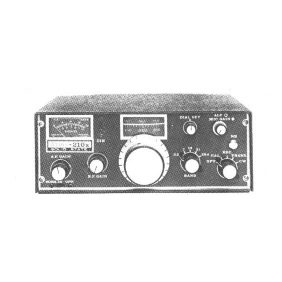
3-2. CONTROLS
Overview of the transceiver's front panel controls and indicators.
3-3. POWER SUPPLY ON/OFF, MOBILE OPERATION
How to turn the transceiver on/off for mobile operation using the Function Switch.
3-4. POWER SUPPLY ON/OFF, 220-CS/200PS.
Using the ON/OFF switch on the 220-CS/200-PS supplies.
3-5. FUNCTION SWITCH
Explanation of the Function Switch positions (OFF, REC, TRANS, CW).
3-6. A. F. GAIN
Function of the AF Gain control for audio volume.
3-7. R. F. GAIN
Function of the RF Gain control for reducing noise and improving reception.
3-8. BAND SELECTOR AND TUNING DIAL, MODEL 21 Ox
How to use the band selector and tuning dial on the Model 210x.
3-9. BAND SELECTOR AND TUNING DIAL, MODEL 215x
How to use the band selector and tuning dial on the Model 215x.
3-10. DIAL SET
Function of the Dial Set control for calibration.
3-11. CARRIER BALANCE
Adjustment of the carrier balance trim pot for minimum carrier.
3-12. S-METER ZERO
Adjusting the S-meter zero trim pot.
3-13. CRYSTAL CALIBRATOR.
How to check and adjust the crystal calibrator against a standard.
3-14. PROPER TUNING OF SINGLE SIDEBAND SIGNALS
Importance of tuning SSB signals correctly for natural voice quality.
3-15. VOICE TRANSMISSION
Procedures for voice transmission using the Mic. button or VOX.
3-16. MODULATION LEVEL
Adjusting the modulation level using the Mic. Gain control.
3-17. ALC
Function and adjustment of the Automatic Level Control (ALC).
3-18. CW TRANSMISSION
Procedures for CW transmission, including frequency shift and keying.
3-19. HEAT SINK
Importance of ventilation and monitoring the heat sink temperature.
SECTION 4 CIRCUIT THEORY
4-1. INTRODUCTION
Introduction to the circuit theory and design of the Atlas transceiver.
4.2. RECEIVER INPUT CIRCUIT.
Explanation of the receiver input circuit design and its benefits.
4-3. SENSITIVITY
Discussion of the transceiver's receiver sensitivity.
4-4. SELECTIVITY
Explanation of the transceiver's selectivity, including the crystal ladder filter.
4-5. OSCILLATOR SWITCHING
Description of oscillator switching for receive/transmit modes.
4-6. TRANSMITTER BROADBAND CIRCUITRY
Explanation of the transmitter's broadband circuitry and lack of tuning.
4-7. RECEIVER BROADBAND CIRCUITRY
Explanation of the receiver's band-switched input filters.
4-8. ALIGNMENT AND TROUBLESHOOTING
Information on chassis schematic, PC board diagrams, and troubleshooting.
4-9. VOLTAGE CHARTS
Guidance on making voltage measurements with a high-impedance meter.
4-10. SIGNAL FREQUENCY RANGES AND LOCAL OSCILLATOR FREQUENCIES
Charts showing signal frequency ranges and VFO/oscillator frequencies.
4-11. PC-100C - FIRST MIXER/FIRST I.F. AMPLIFIER
Detailed circuit description of the PC-100C module.
4-12. PC-200C Second I.F. Amplifier, Second Mixer, Mic. Amp., S-Meter Amp.
Circuit description of the PC-200C module, including its functions.
4-13. PC-300C Receiver Audio, Oscillator Switch
Description of the PC-300C module for receiver audio and oscillator switching.
4-14. PC-500D/520A Pre-Amplifier, Driver, Power Amplifier, SWR Protect
Circuit description of the PC-500D/520A modules for amplification and SWR protection.
4-15. PC-400C VFO Circuit Board and Tuning Circuits
Explanation of the PC-400C VFO circuit and tuning sections.
4-16. PC 600 Carrier Oscillator, Buffer Amplifier
Description of the PC-600 module for carrier oscillation and buffering.
4-17. PC-800C/1200 Receiver Input Tuning
Explanation of the PC-800C/1200 receiver input tuning components.
4-18. PC-820 100 kHz Crystal Calibrator
Description of the PC-820 100 kHz crystal calibrator circuit.
4-19. PC-900C Transmitter Input Tuning
Explanation of the PC-900C transmitter input tuning components.
4-20. PC-1010/1020 Low Pass Filters
Description of the PC-1010/1020 low pass filters.
4-21. PC-1100A SWR Bridge, Antenna Relay Circuitry
Circuitry of the PC-1100A SWR bridge and antenna relay.
SECTION 5 ACCESSORIES
5-1. NOISE BLANKER MODEL PC-120
Description of the PC-120 noise blanker accessory and its operation.
5-2 MODEL 10X CRYSTAL OSCILLATOR
Description of the Model 10x crystal oscillator accessory for frequency control.
5-3. Model MT-1
Description of the MT-1 transformer for mobile antenna impedance matching.
5-4. Model VX-5 VOX
Description of the VX-5 VOX accessory.
5-5. Model DD-6B Digital Dial
Description of the DD-6B Digital Dial with frequency counter capability.
ATLAS A WARRANTY
THE ATLAS-210x/215x IS GUARANTEED UNDER THE FOLLOWING SCHEDULE:
Details the warranty schedule for the Atlas transceiver.
Need help?
Do you have a question about the 215x and is the answer not in the manual?
Questions and answers