3-4 Power Supply On/Off, 220-CS/200-PS ....3-5 Function Switch 3-6 A. F.Gain ........3-7 R. F.Gain ........3-8 Band Selector and Tuning Dial, Model 210X
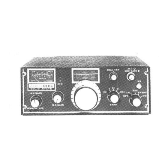
 ....3-9 Band Selector and Tuning Dial, Model 215X 3-10 Dial Set ........3-11 Carrier Balance 3-12 S-Meter Zero ........
Page 3
Front Panel of ATLAS 210x ......... 16 Rear Panel of ATLAS 210x/215x ......16 ATLAS 210x/215x Modular Design and Plug-in P.C. Boards .... 21 ATLAS 210x/215x Block Diagram ......22 Crystal Ladder Filter Selectivity Characteristics ...
1-1. INTRODUCTION The Atlas 210x Transceiver is designed for single sideband and CW communications in the 10, 15, 20, 40, and 80 meter amateur radio bands. The Atlas 215x covers 15, 20, 40, 80, and 160 meters. They employ all solid state circuitry, with modular construction.
28400 - 29400 kHz CIRCUIT DESIGN: All solid state, 4 IC's, 18 transistors, 31 diodes. Single NOTE: The 10 meter band on the 210x may be easily conversion, 5520 kHz I.F. owner adjusted to cover any 1000 kHz portion of the band.
RECEIVER SPECIFICATIONS CIRCUIT DESIGN: Front end design provides exceptional immunity overload cross variation from 5 microvolts to more than 3 volts. modulation, matching or out performing the best OVERALL GAIN: Requires less than 1 microvolt vacuum tube designs. Signals are converted directly signal for 0.5 watts audio output.
CW KEYING: Manual send-receive.Semi-break-in with CW accessory installed in AC power supply console. Plug requirement: standard % in. diam. 3 circuit phone plug. TRANSMIT CONTROL: Press to talk with Mic. button, or manual transmit with Function Switch on AUDIO FIDELITY: 300 to 3000 Hertz, plus or minus front panel.
7.5 A.H. It comes in a simulated leather case with shoulder strap, and includes an AC charger. Your Atlas dealer may handle Globe products. Also, it is anticipated that Atlas Radio may have the GC1400 pack available for Atlas dealers. Otherwise, you may contact Globe directly for reference to a Globe dealer.
22. GENERAL INFORMATION 2-3. D.C. POWER. The Atlas transceiver is designed to operate on a power source of 12-14 volts D.C. Power can be delivered to the transceiver via the Deluxe Mounting Kit (DMK), D.C. Cable (DCC), Cigarette Lighter Cable (CLC), Portable Battery Pack, 220-CS AC Console, or 200-PS Portable AC Supply.
Page 10
The 200-PS operates on either 110 volts AC or 220 volts AC, selected by changing fuses. It is anticipated that a plastic or simulated leather carrying case will be available from Atlas Radio for the 200-PS supply as well as for the transceiver in the near future.
2-18. REMOTE CW TRANSMIT SWITCH FOR ATLAS TRANSCEIVERS. The Atlas transceivers have a function switch which provides for switching into the CW Transmit mode. However, it requires switching from the RLC. to TRANS., and then to the CW position. This procedure is rather awkward, and the circuit shown below (Figure 2-1) provides a more convenient system.
2-21. LINEAR AMPLIFIER CONNECTIONS. Figure 2-2 illustrates how to connect a linear amplifier to the Atlas transceivers. ALC output from the linear may be connected to Pin 4 on the AUX. socket plug. The ALC control voltage from the linear MUST be positive going. Most linears with an ALC output circuit are negative going.
Use proper terminal lugs at these points for connecting the leads. Battery clamps and terminals should be cleaned and tightened periodically. Anti-corrosion grease is a good recommendation. All other electrical connections under the hood: alternator, regulator, ignition coil,etc.,should also be checked and tightened. Figure 2-2. Linear Amplifier Connections to ATLAS Transceiver...
Figure 2-3. Deluxe Plug-in Mobile Mounting Kit Installation 2-24. MOBILE BRACKET KIT (MBK). This kit includes: One 9-inch and two 12-inch cadmium plated steel mounting bars with screws. Figure 2-4 illustrates how the transceiver can be hung under the dash, or mounted over the transmission hump.
No. 12 gauge stranded wire of the automotive type. A 20 amp. fuse or circuit breaker should be installed in the positive lead. Figure 2-5 illustrates the proper connections required between the battery and the Atlas transceiver. CAUTION IT IS EXTREMELY IMPORTANT THAT PROPER POLARITY BE OBSERVED.
In fixed station installations, the use of the 220-CS eliminates the necessity for making D.C. power connections. The only requirement is that the Atlas Transceiver be firmly seated in the console. When installing the transceiver in the console, always make sure that the unit is pushed all the way into the console. This will insure that all power, Mic, and speaker connections are firmly made.
2.33. FIXED STATION ANTENNAS On 10, 15, and 20 meters a doublet and most beam antennas will match quite well across the entire band. On 40 meters a doublet tuned for phone band center will match quite well across the band. On 75 meters the average doublet will have a bandwidth of about 100 kc for SWR of 1.5 or less.
The purpose of the R.F. Gain control is to permit decreasing the between speech noise level, thus providing more pleasing reception. The AGC system in the ATLAS transceiver has a tremendous dynamic signal range. With full R.F. Gain, sensitivity will automatically return to maximum in the absence of a signal, accompanied by a natural increase in background noise.
2 kHz apart on 10 meters. 3-9. BAND SELECTOR AND TUNING DIAL, MODEL 215x The number on the band selector reads in MegaHertz, the same as on Model 210x, except that it has the 1.8 MHz band instead of the 28.4 MHz.
3-16. MODULATION LEVEL Modulation level is adjusted with the Mic. Gain control. When the transceiver is coupled into a proper 52 ohm load, voice peaks will be reaching about 16 amps., although the ammeter cannot respond quickly enough to show these peaks.
Page 22
CAUTION GREATEST DANCER POWER OUTPUT TRANSISTORS OVERHEATING. THE BLACK ANODIZED HEAT SINK IS DESIGNED TO COOL THE TRANSISTORS ADEQUATELY UNDER NORMAL OPERATING CONDITIONS, BUT AS WITH ANY ELECTRONIC OR MECHANICAL DEVICE, IT IS UP TO THE OPERATOR TO MAINTAIN NORMAL CONDITIONS, AND NOT ABUSE THE EQUIPMENT. THE MAXIMUM SAFE TEMPERATURE OF THE HEAT SINK NEAR THE OUTPUT TRANSISTORS IS ABOUT 150 DEC.
R.F. amplification prior to frequency conversion. The fact is that the Atlas is at least as sensitive as the best of the tube or solid state receivers having R.F. Amplifiers. This is due largely to the very low noise figure of the double balanced diode ring mixer, followed by a low noise I.F.
In receive mode the first mixer heterodynes the antenna signal with VFO injection. In transmit mode the first mixer functions as a balanced modulator with carrier oscillator injection and Mic. amp. input. In both modes the first mixer output is at the intermediate frequency (I.F.) of 5520 kHz. In receive mode the second mixer functions as a product detector with carrier oscillator injection.
VFO trimmers are reached by removing the transceiver top cover. Adjustment of a trimmer for lower or higher frequency will move the entire band down or up, and will came the dial Male to read less accurately. Special frequency ranges with accurate dial calibration are available from Atlas on special order. Band, MHz Frequency Range, KHz, with Crystal Oscillator 1.8*...
4-11. PC-100C - FIRST MIXER/FIRST I.F. AMPLIFIER In the receive mode, the R.F. signal is coupled from terminal 1 of PC-100C to the primary of the trifllar toroid transformer LI 01, through capacitors C101 and C110, to the double balanced diode ring mixer, D101 through D104.
4-12. PC-200C Second I.F. Amplifier, Second Mixer, Mic. Amp., S-Meter Amp. In receive mode, the I.F. signal from the 8 pole Crystal Ladder Filter is coupled through terminal 3 of PC-200C to the Integrated Circuit Q201, which is the Second I.F. Amplifier. The signal is amplified and coupled through the tuned circuit that consists of R203, C205 and L201, which is tuned to the I.F.
4-13. PC-300C Receiver Audio, Oscillator Switch The audio output from PC-200C is coupled through terminal 20 of PC-300C, through C303 to pin 12 of the Integrated Circuit Q301, which is the A.F. Amplifier. The output of Q301 is coupled through C302 to terminal 22 of PC-300C to the AF GAIN control on the front panel, then back through terminal 12 of PC-300C to the input of the AF Power Amplifier Q302.
4-14. PC-500D/520A Pre-Amplifier, Driver, Power Amplifier, SWR Protect The R.F. output from PC-200C is coupled through the Transmitter Input Tuning circuit (PC-900) to the input connection on PC-520A. From the input connection, the signal is coupled through C504 to the base of the Pre- Amplifier Q501, where it is amplified and coupled through C501 to the base of Q502 for further amplification.
13 of PC-300C. From terminal 13 of PC-300C, the VFO signal is fed to the F.E.T. Oscillator Switch. Voltage regulation for the VFO circuits is provided by Ql and D2 on the main chassis. VFO FREQUENCY CHART, MODEL 210x I.F. at 5520 kHz...
4-16. PC 600 Carrier Oscillator, Buffer Amplifier PC-600 consists of those components necessary to generate the normal carrier frequency of 5520 kHz, and the opposite sideband frequency of 5523.3 kHz. Crystal X602 is the Normal sideband crystal, and X601 is the opposite sideband crystal.
4-18. PC-820 100 kHz Crystal Calibrator The 100 kHz crystal calibrator circuit is assembled on PC-820. Its schematic diagram is shown in Figure 4-11A. It is actuated by the function switch in the "CAL" position. Frequency is adjusted by trimmer C821 against a known standard such as WWV.
Trimmer capacitors are located on the board for fine tuning the circuits. These trimmers are factory set and require no further adjustments. MODEL 210x PC-900C CIRCUIT COMPONENTS Transmitter Input Tuning C901 ....240 pF 10% Disc L901......
4-20. PC-1010/1020 Low Pass Filters PC-1010/1020 is a band switched two section low pass filter. The filter is connected between the output of the Power Amplifier (PC-500D) and the antenna connector to suppress harmonics 30 dB or more. The filters are designed for a 50 ohm load and it is important that the load be quite close to 50 ohms, non-reactive.
4-21. PC-1100A SWR Bridge, Antenna Relay Circuitry The relay, RL1101, switches the antenna circuit from the PC-800C receiver input filters over to the PC-500D power amplifier output. The other pole of this relay connects to the AUX. rear socket, and is intended for switching a Linear Amplifier, as described in Section 2-21.
5-1. NOISE BLANKER MODEL PC-120 The Noise Blanker is a plug-in accessory which replaces the standard PC-100C R.F. board in Atlas transceivers. If Noise Blanker is owner or dealer installed, a threshold control which is attached to the PC-120B by a 3 wire cable, must be installed on the front panel.
INSTALLATION: A 9 pin Noval socket on the back of the Atlas transceiver is labeled EXT. OSC. The lOx plugs into this socket. It will be necessary to remove the two jumper wires plugged in between pins 2 and 3; and pins 5 and 6. Once the wires have been removed, the transceiver VFO will not function unless the lOx is plugged in and switched to its VFO position, or the dummy jumper, which is furnished with the lOx , is inserted in the EXT.
CALCULATION OF CRYSTAL FREQUENCY: For operation on lower sideband (LSB): Bands 160, 75, 40 meters, (Sideband Selector in NORM. position.) Crystal Frequency equals Signal Frequency plus 5520 kHz. Example: 4020 + 5520 = 9540 Bands 20 and 15 meters, (Sideband Selector in OPP. position.) Crystal Frequency equals Signal Frequency minus 5523.3 kHz Example: 14,370 - 5523.3 = 8846.7 kHz For operation on upper sideband (USB): Bands 160, 75, 40 meters,...
With the Atlas MT-1 transformer a tap selection will be found which will provide SWR readings of 1.4 or less when using the common type mobile antennaes, such as those manufactured by Nutronics, Swan, and HyGain.
• Measures 1 3/8 high x 5 3/8 wide x 5 7/8 deep. ATTENTION SWAN OWNERS In addition to operating with all Atlas transceivers, the DD-6B can be made to operate with Swan models 350C, 500C, 500CX, 700CX, 270, 270B, 300B, 600R, and 600T.
Page 56
MODEL 210x/215x CHASSIS COMPONENTS PC-100C ....First I.F. Amplifier, First Mixer Printed Circuit Board or PC-120 ......Optional Noise Blanker, 1st I FAmp , 1st Mixer PC-200C ..
Page 57
ATLAS RADIO, INC. 417 Via Del Monte Oceanside, California 92054 (714)433-1983...
Need help?
Do you have a question about the 210x and is the answer not in the manual?
Questions and answers