Advertisement
SERVICE
MIMI MIMI COMPONENT SYSTEM
Disc 1
Disc Selection / Direct Play
On/Standby
R
Demo
AI Off
Timer
Timer
/Sleep
On/Off
/Clock
TUNER
C
D
Band
Mono/ST
Memory
Repeat
Program
REC/Pause
CD SYNC.
Shuffle
REC Lock
Phones
Down
Disc 1
Disc Selection / Direct Play
On/Standby
R
Demo
AI Off
Timer
Timer
/Sleep
On/Off
/Clock
TUNER
C
D
Band
Mono/ST
Memory
Repeat
Program
REC/Pause
CD SYNC.
Shuffle
REC Lock
Down
Phones
Disc 2
Disc 3
Disc Change
Volume
+
–
TAPE
AUX
Deck 1/2
REV mode
TAPE
TAPE REC
Normal
HI-Speed
Tuning Mode
Up
Disc 2
Disc 3
Disc Change
Volume
+
–
TAPE
AUX
Deck 1/2
REV mode
TAPE
TAPE REC
Normal
HI-Speed
Tuning Mode
Up
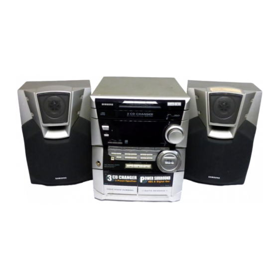
3 CD CHANGER
MINI MINI COMPONENT
MAX-N50/52/53/54/55/57
Manual
2. Exploded Views and Parts List
5. PCB Diagrams
CONTENTS
Advertisement
Table of Contents

Related Manuals for Samsung MAX-N52


Summarization of Contents
Alignment and Adjustments
Tuner Alignment
Details FM THD, FM Search Level, and AM(MW) I.F adjustments with diagrams and parameters.
AM/MW/LW/SW Tuner Adjustment
Specifies SSG frequency, adjustment points, and adjustments for AM/MW, LW, SW1, SW2 bands.
Cassette Deck Adjustments
Procedures for adjusting tape speed, playback level for Deck 1/2, and REC Bias Voltage.
Block Diagrams
Main Part Block Diagram (Common)
Block diagram illustrating the common main part of the audio system, showing signal flow.
Main Part Block Diagram (MAX-N57)
Block diagram specific to the MAX-N57 model, showing main part connections.
CD Part Block Diagram (Common)
Block diagram for the common CD playback section, detailing the CD mechanism and digital signal processor.
Schematic Diagrams
CD Section Schematic
Schematic diagram for the CD section, showing component connections and ICs.
Main PCB Schematic (Common)
Schematic diagram for the common main PCB, detailing ICs and circuit configurations.
Main PCB Schematic (MAX-N57)
Schematic diagram specific to the MAX-N57 model's main part circuit.
Front PCB Schematic (Common)
Schematic diagram for the common front panel control and display section.
Tuner Section Schematic (Common)
Schematic diagram for the common tuner section, detailing FM/AM reception circuits.
Need help?
Do you have a question about the MAX-N52 and is the answer not in the manual?
Questions and answers