Table of Contents
Advertisement
In the interests of user-safety (Required by safety regulations in some countries) the set should be restored to its orig-
inal condition and only parts identical to those specified should be used.
CAUTION ............................................................2
Precautions for using lead-free solder ................3
CHAPTER 1. OPERATION MANUAL
[1] SPECIFICATIONS ..................................................4
[2] OPERATION MANUAL ...........................................5
[3] DIMENSIONS .......................................................10
CHAPTER 2. REMOVING OF MAJOR PARTS
[1] REMOVING OF MAJOR PARTS ..........................12
CHAPTER 3. ADJUSTMENT PROCEDURE
[1] ADJUSTMENT PROCEDURE ..............................20
[2] SERVICE MODE ...................................................26
[3] SOFTWARE UPGRADE PROCEDURE.............
[1] TROUBLESHOOTING TABLE..............................28
[1] MAJOR IC INFORMATIONS.................................46
CHAPTER 6. BLOCK DIAGRAM/WIRING DIAGRAM
[1] BLOCK DIAGRAM ...............................................61
Parts marked with "
" are important for maintaining the safety of the set. Be sure to replace these parts with specified ones for maintaining the
safety and performance of the set.
SERVICE MANUAL
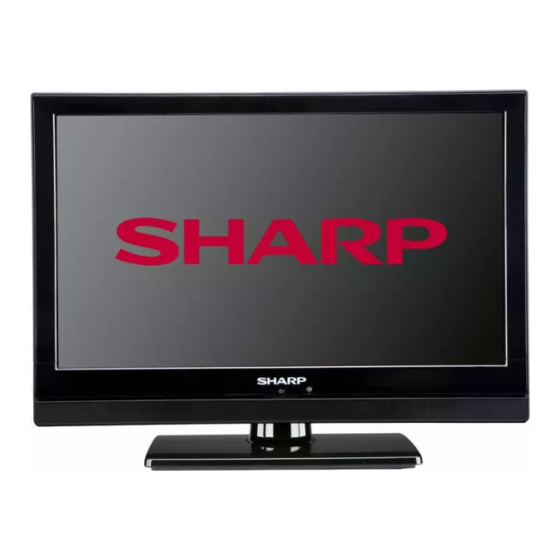
LCD COLOUR TELEVISION
MODELS
CONTENTS
[2] POWER MANAGEMENT BLOCK DIAGRAM ......63
[4] WIRING DIAGRAM ...............................................65
[1] MAIN UNIT PRINTED WIRING BOARD ................68
[2] POWER UNIT PRINTED WIRING BOARD ...........72
[3] KEY UNIT PRINTED WIRING BOARD .................76
[4] IR UNIT PRINTED WIRING BOARD .....................78
[1] MAIN SCHEMATIC DIAGRAM .............................80
[2] POWER SCHEMATIC DIAGRAM ......................113
[3] KEY SCHEMATIC DIAGRAM .............................116
[4] IR SCHEMATIC DIAGRAM .................................118
..
27
[1] SPARE PARTS LIST............................................120
[2] CABINET PARTS ................................................186
[3] SUPPLIED ACCESSOORIES..............................190
[4] PACKING PARTS.................................................191
1
LC-19S7E-BK LC-26S7E-BK LC-32S7E-BK
LC-19S7E-BK
LC-26S7E-BK
LC-32S7E-BK
This document has been published to be used for
after sales service only.
The contents are subject to change without notice.
No.
Advertisement
Table of Contents

Summarization of Contents
SAFETY PRECAUTION
IMPORTANT SERVICE SAFETY PRECAUTION
Guidelines for qualified technicians performing service work safely and following guidelines.
BEFORE RETURNING THE RECEIVER (Fire & Shock Hazard)
Essential safety checks to perform before returning the receiver to the user.
SAFETY NOTICE
Highlights special safety parts and the importance of using genuine replacement parts.
Precautions for using lead-free solder
Using lead-free wire solder
Proper use of lead-free wire solder for repairs and its properties.
Soldering
Best practices for soldering with lead-free solder to avoid damage.
CHAPTER 1. OPERATION MANUAL
[1] SPECIFICATIONS
Technical specifications for the 19", 26", and 32" LCD Colour Television models.
[2] OPERATION MANUAL
Explains remote control operations and TV functions.
[3] DIMENSIONS
Physical dimensions of the different TV models.
CHAPTER 2. REMOVING OF MAJOR PARTS
[2.1] REMOVING OF MAJOR PARTS(LC-19S7E-BK)
Step-by-step guide for disassembling major parts of the 19-inch model.
REMOVING OF MAJOR PARTS(LC-26S7E-BK&LC-32S7E-BK)
Disassembly instructions for major parts of the 26-inch and 32-inch models.
CHAPTER 3. ADJUSTMENT PROCEDURE
[1] ADJUSTMENT PROCEDURE
Details on picture and sound adjustments available via the OSD menu.
[2] SERVICE MODE
Instructions for entering and navigating the service mode menu.
[3] SOFTWARE UPGRADE PROCEDURE
Steps for updating the TV's firmware via USB.
CHAPTER 4. TROUBLESHOOTING TABLE
[1] TROUBLESHOOTING TABLE (19”)
Common problems and their solutions for the 19-inch model.
[1] TROUBLESHOOTING TABLE(26“&32”)
Common problems and their solutions for the 26/32-inch models.
CHAPTER 5. MAJOR IC INFORMATIONS
[1] MAJOR IC INFORMATIONS
Detailed information on key integrated circuits like U4201.
CHAPTER 6. BLOCK DIAGRAM/WIRING DIAGRAM
Block Diagrams
System architecture block diagrams for 19-inch and 26/32-inch models.
Power Management Schematics
Diagrams detailing the power management circuits for different models.
Wiring Diagrams
Interconnection diagrams for various models.
CHAPTER 7. PRINTED WIRING BOARD
Main Unit PWBs
Top and bottom views of the main PCB for 19, 26, and 32-inch models.
Power Unit PWBs
Top and bottom views of the power supply PCB for different models.
Key Unit PWBs
Top and bottom views of the key input PCB.
IR Unit PWBs
Top and bottom views of the IR receiver PCB.
CHAPTER 8. SCHEMATIC DIAGRAM
Main Schematic Diagrams
Main circuit schematics for 19-inch and 26/32-inch models.
Interface and Component Schematics
Schematics for various interfaces (Video, SCART, HDMI, USB, Audio, Panel, etc.).
Power Supply Schematics
Detailed power supply schematics for different model sizes.
Control and IR Schematics
Schematics for keypad and IR receiver modules.
CHAPTER 9. Parts Guide
Spare Parts Lists
Comprehensive lists of all spare parts for 19, 26, and 32-inch models.
Cabinet Parts
Exploded diagrams and lists of cabinet components for all models.
Supplied Accessories
Details of included accessories like remote, cables, and manuals.
Packing Parts
Lists of packing materials for shipping and protection.


Need help?
Do you have a question about the LC-26S7E-BK and is the answer not in the manual?
Questions and answers