Table of Contents
Advertisement
Quick Links
Advertisement
Table of Contents

Related Manuals for Hyundai Seasall S270P Series


Summary of Contents for Hyundai Seasall S270P Series
-
Page 2: Table Of Contents
INSTALLATION & OPERATION MANUAL S270 Series Engines TABLE OF CONTENTS ABOUT THIS MANUAL ……………………………………………………………….…..…. SAFETY PRECAUTIONS ……………………………………………………...…….………… APPROXIMATE CONVERSIONS FROM STANDARD………………………….………….. …………………………………………………….………… CHAPTER 1 ENGINE OVERVIEW ……………………………………………………… 1. ENGINE COMPONENTS 2. ENGINE SUSPENSION ………. ……………………………………………….. ………………………………………………….…. 3. ENGINE IDENTIFICATION 4. SCHEMATIC DIAGRAM OF COMMON RAIL DIESEL ENGINE ……... 5. - Page 3 INSTALLATION & OPERATION MANUAL S270 Series Engines TABLE OF CONTENTS CHAPTER 7 ELECTRICAL SYSTEM …………………………………………….…….…….. 1. BATTERY CABLE CONNECTIONS …………………………..……………. 2. BATTERY CHECKS …………………………………………………..……. 3. FUSE AND RELAY …………………………………………..…………...….. CHAPTER 8 INSTRUMENT SYSTEM ……………………...………………….………..1. INSTRUMENT CONNECTIONS …………..………………….…...….……. 2. CUT-OUT FOR GAUGE ……………………...……………….….…….….. 3.
-
Page 4: About This Manual
This engine installation and operation manual is provided as guidance for the installation of a Hyundai SeasAll engine in a boat, and to describe engine operation. Its purpose is to provide technical information to aid in performing an effective engine installation so as to achieve both maximum performance and service life. -
Page 5: Safety Precautions
Wait until the engine • Do not use the engine for a purpose other than is fully cool to do inspection and maintenance. what is intended by Hyundai SeasAll. Do not modify the performance of the supplied engine REFUELING without the express permission of Hyundai SeasAll. -
Page 6: Approximate Conversions From Standard
INSTALLATION & OPERATION MANUAL S270 Series Engines APPROXIMATE STANDARD CONVERSIONS MULTIPLY MULTIPLY SYMBOL SYMBOL SYMBOL SYMBOL 0.039 inch inch 25.4 LENGTH inch LENGTH inch 2.54 3.28 0.3048 0.0016 645.2 AREA AREA 10.764 0.093 in ³ 0.061 in³ 16.388 0.06 61.023 in³... -
Page 7: Chapter 1 Engine Overview
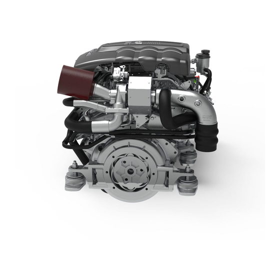
INSTALLATION & OPERATION MANUAL S270 Series Engines CHAPTER 1 ENGINE OVERVIEW 1. ENGINE COMPONENTS 1. ECU Box 7. Engine Oil Gauge 2. Coolant Expansion Tank 8. Acceleration Lever Sensor 3. Engine Oil Cap 9. Seawater Pump 4. Engine Oil Filter 10. - Page 8 INSTALLATION & OPERATION MANUAL S270 Series Engines 2. ENGINE HANGER 1) To lift the engine, first remove the engine cover. You will find three engine eyes (see figure). 2) To avoid damage to the engine or operator, take care that engine lift chains or belts do not hit or touch surrounding parts during engine lifting.
-
Page 9: Engine Identification
INSTALLATION & OPERATION MANUAL S270 Series Engines 3. ENGINE IDENTIFICATION Engine identification is affixed to the engine block and the ECU box (see figure). SERIAL NUMBER ON THE ENGINE BLOCK NAME PLATE ON THE ECU BOX Engine Family D6EB Engine Type S270X... -
Page 10: Schematic Diagram Of Common Rail Diesel Engine
INSTALLATION & OPERATION MANUAL S270 Series Engines 4. SCHEMATIC DIAGRAM OF COMMON RAIL DIESEL ENGINE Common rail Feed Rail pressure Sensor Return Rail pressure Pump regulator pressure valve regulator Air filter valve High Boost Air Temp. pressure pressure Return sensor pump sensor Intercooler... -
Page 11: Technical Data
INSTALLATION & OPERATION MANUAL S270 Series Engines 5. TECHNICAL DATA S270S S270P S270J Engine type 4-stroke, 24-valve After-cooled, direct-injection, water cooling Output PS(kW) 270PS (199) rpm at full load 3800 Cylinders Ignition sequence 1-2-3-4-5-6 Displacement [cm 2959 Bore [mm] Stroke [mm] Compression ratio 17.3±0.5 : 1 57.6... -
Page 12: Performance Curves
INSTALLATION & OPERATION MANUAL S270 Series Engines 6. PERFORMANCE CURVE S270S & S270P MODEL Torque 1000 1500 2000 2500 3000 3500 4000 1000 1500 2000 2500 3000 3500 4000 Engine Speed (rpm) *F.C : Fuel Consumption - 11 -... - Page 13 INSTALLATION & OPERATION MANUAL S270 Series Engines S270J MODEL 1000 1500 2000 2500 3000 3500 4000 1000 1500 2000 2500 3000 3500 4000 Engine Speed(rpm) *F.C : Fuel Consumption - 12 -...
-
Page 14: Belt Installation & Engine Dimesions
INSTALLATION & OPERATION MANUAL S270 Series Engines 7. BELT INSTALLATION & ENGINE DIMENSIONS V-RIBBED BELT INSTALLATION MODEL : S2-ENG SERIES AN ALTERNATOR DP DRIVE PULLEY IDLER PULLEY PS POWER STEERING TP TENSIONER PULLEY WP WATER PUMP PULLEY MerCruiser Bravo One X Diesel Front view Side view ... - Page 15 INSTALLATION & OPERATION MANUAL S270 Series Engines MerCruiser Bravo Three X Diesel Front view Side view ZF 63 A Front view Side view - 14 -...
- Page 16 INSTALLATION & OPERATION MANUAL S270 Series Engines ZF 63 C Front view Side view Waterjet adapter without ZF 63 C Front view Side view - 15 -...
-
Page 17: Chapter 2 Engine Mount System
Engine Mounts > -. Engine installation must be done by a qualified Hyundai-SeasAll alignment tool(5 Step) technician. Hyundai SeasAll engines must be aligned using the genuine Hyundai SeasAll alignment tool Otherwise the drive coupler will be damaged. MerCruiser alignment tool(4 Step) -
Page 18: Bellhousing Fixing
) to keep the bolt from turning while adjusting the engine height by turning the middle nut ( ). Adjust the engine height until the Hyundai SeasAll alignment tool can be properly inserted. 2) After alignment, place washer ( ) on top of... -
Page 19: Chapter 3 Cooling & Exhaust System
INSTALLATION & OPERATION MANUAL S270 Series Engines CHAPTER 3 COOLING SYSTEM & EXHAUST SYSTEM 1. SCHEMATIC DIAGRAM OF ENGINE COOLING CIRCUIT EX-MANIFOLD CABIN HEATER AIR FILTER CONNECTOR TURBO CHARGER THERMOSTAT COOLANT PUMP EXHAUST ELBOW EX-MANIFOLD OIL COOLER EXPANSION TANK HEAT EXCHANGER E-VGT COOLER INTERCOOLER SEA WATER... -
Page 20: Seawater Flow
INSTALLATION & OPERATION MANUAL S270 Series Engines 2. SEAWATER FLOW – OPEN COOLING CIRCUIT Water strainer ← Water valve ← Water pickup ↓ ① Seawater pump ↓ ② Intercooler ↓ ③ Heat exchange ⑤ EVGT cooler ↓ ④ Oil cooler ↓... -
Page 21: Seawater Pump
INSTALLATION & OPERATION MANUAL S270 Series Engines 4) To clean strainer filter, • Stop the engine and close the water valve • Remove the filter cap • Remove the filter element, flush it thoroughly with clean water or compressed air •... - Page 22 INSTALLATION & OPERATION MANUAL S270 Series Engines CHECKING SEA WATER PUMP & IMPELLER • Stop the engine and close the water valve • Remove the impeller housing cover • Remove the impeller from inside the seawater pump • Check the condition of impeller and bushing •...
-
Page 23: Engine Coolant
INSTALLATION & OPERATION MANUAL S270 Series Engines 3. THE FLOW OF ENGINE COOLANT – CLOSED COOLING CIRCUIT THERMOSTAT CLOSED CONDITION ① Coolant engine outlet ↓ ② Exhaust manifolds (both) ↓ Thermostat closed (opening temp 82℃) ↓ ③ Coolant engine inlet ... - Page 24 INSTALLATION & OPERATION MANUAL S270 Series Engines 3) If the coolant level is low, add enough specified coolant to provide protection against freezing and corrosion. Bring the level to MAX, but do not overfill. 4) If frequent additions are required, see an authorized dealer for a cooling system inspection.
-
Page 25: Cabin Heater Connection
2) After connecting cabin heater lines, engine coolant must be refilled and checked. 3) Please check coolant flow direction, as shown in the figure. 4) If in doubt, please contact your nearest Hyundai SeasAll dealer. *After installing a cabin heater and refilling the system, the coolant in the coolant expansion tank may initially overflow. -
Page 26: Exhaust System
S270 Series Engines 4. EXHAUST SYSTEM 1) Your Hyundai SeasAll engine’s exhaust system consists of a coolant-cooled exhaust manifold and a seawater-cooled exhaust elbow (water injected wet exhaust system). 2) The vessel’s exhaust pipe line should not be made too long or to bend. The maximum back pressure of the exhaust gas should be under 50kPa. -
Page 27: Chapter 4 Fuel System
INSTALLATION & OPERATION MANUAL S270 Series Engines CHAPTER 4 FUEL SYSTEM The fuel supply system of this engine is diesel common rail direction injection. In order to optimize engine combustion, its maximum injection pressure is up to 1800 bar. Multi-injection is possible thanks to the quick response of the piezo type injector. -
Page 28: Fuel Flow
INSTALLATION & OPERATION MANUAL S270 Series Engines 1. FUEL FLOW Fuel tank ↓ Auxiliary fuel filter ↓ ① Fuel pump (low pressure) ↓ ② Fuel filter with water detection sensor ↓ ③ High pressure pump ↓ ④ Common rail ↓ ⑤... -
Page 29: Acceleration Sensor And Control Lever
INSTALLATION & OPERATION MANUAL S270 Series Engines 3. ACCELERATION SENSOR AND CONTROL LEVER When installing control lever cable to acceleration 60 mm sensor, be sure that the acceleration sensor lever is fully released to the idle position and fully pulled to the full-load position. -
Page 30: Recommended Fuel Quality
• After starting the engine, check to make certain the fuel filter warning light is off CAUTION HYUNDAI SEASALL’S GUARANTEES OR WARRANTIES ARE VOID IN CASES WHERE DAMAGE TO THE FUEL INJECTON COMPONENTS (HIGH PRESSURE PUMP, INJECTORS, ETC.) CAN BE ATTRIBUTED TO THE USE OF UNQUALIFIED FUELS. -
Page 31: Chapter 5 Air Intake System
INSTALLATION & OPERATION MANUAL S270 Series Engines CHAPTER 5 AIR INTAKE SYSTEM 1. ENGINE AIR CONSUMPTION -. The engine needs to have a proper volume of intake air for combustion. This requires a minimum internal area of air supply ducting the area can be calculated by using the following formula: Number of Length of pipe (Meters) - Page 32 S270 Series Engines AIR FILTER MAINTENANCE • The original Hyundai SeasAll air cleaner may be cleaned and reused. • If the air filter is very dirty, it can increase airflow resistance and reduce flow of air to the engine. This can result in reduced power and fuel efficiency.
-
Page 33: Chapter 6 Lubrication System
INSTALLATION & OPERATION MANUAL S270 Series Engines CHAPTER 6 LUBRICATION SYSTEM 1. ENGINE OIL FLOW Seawater Camshaft Pump Pressure regulator valve Oil Pump Cyl Head Piston Cooling Jet Oil Cooler Hydraulic Lash Turbine Adjuster Chain & Tensioner Filter To Cyl Head Crankshaft Supply Return... -
Page 34: Engine Oil Level Checks
INSTALLATION & OPERATION MANUAL S270 Series Engines 2. ENGINE OIL LEVEL CHECKS • The engine oil level must be checked at regular intervals. • Be sure the boat is level. • Start the engine and allow it to reach normal operating temperature. -
Page 35: Engine Oil Extaction Pump
USED OIL MUST BE STORED IN A SAFE PLACE AWAY FROM CHILDREN AND SOURCES OF IGNITION. IF YOU HAVE A USED OIL DISPOSAL PROBLEM, PELASE HAVE THE ENGINE OIL CHANGED BY YOUR NEAREST HYUNDAI SEASALL SERVICE DEALER. - 34 -... -
Page 36: Chapter 7 Electrical System
INSTALLATION & OPERATION MANUAL S270 Series Engines CHAPTER 7 ELECTRICAL SYSTEM 1. BATTERY CABLE CONNECTIONS 1) The size of battery cable should be at least 40mm and no longer than 4m. 2) If the cable is longer than 4m. the size should be at least 50mm 3) Recommended battery capacity is over 200 amperes. -
Page 37: Battery Checks
INSTALLATION & OPERATION MANUAL S270 Series Engines 2. BATTERY CHECKS Battery inspection is very important in electronic control engines: You must check the battery condition regularly. LOAD TEST 1) Perform the following steps to complete the load test procedure for maintenance-free batteries. -
Page 38: Fuse And Relay
ECU box. Always replace a blown fuse with one of the same rating. If the replacement fuse blows, this indicates an electrical problem. Avoid using the system involved and immediately consult an authorized Hyundai SeasAll dealer. Fuses in the ECU Box System Power: 30Amp... - Page 39 INSTALLATION & OPERATION MANUAL S270 Series Engines 3.2 RELAYS Relays in the ECU Box 1) Main Relay: 30 Amp 2) Oil Extraction Pump Relay: 30 Amp 3) Fuel Pump Relay : 30 Amp 4) Fuel Heater Relay: 30 Amp 5) Start Solenoid Relay: 30 Amp 6) Glow Relay: 70 Amp •...
-
Page 40: Chapter 8 Instrument System
INSTALLATION & OPERATION MANUAL S270 Series Engines CHAPTER 8 INSTRUMENT SYSTEM 1. INSTRUMENT CONNECTIONS Main EOI SeasLink Dongle (Connect to OBD Terminal in EOI) Dual EOI (Opt) Engine to EOI wiring (5m/7m/10m/15m) [00112-7D195, 00112-5S197, 00112-5S190, 00112-5S196] EOI to RPM gauge (Ø 85) Wiring [00113-5S104, 00113-5S1G4(Chrome)] EOI to coolant temp gauge (Ø... - Page 41 INSTALLATION & OPERATION MANUAL S270 Series Engines 1.1 STANDARD INSTRUMENTS Ø 5 RPM Gauge Coolant Temperature Gauge Battery Voltmeter Gauge Ignition Key switch NOTE: Gauge panel (show above) is not standard but available as an option 1.2 COOLANT TEMPERATURE GAUGE •...
- Page 42 INSTALLATION & OPERATION MANUAL S270 Series Engines 1.3 RPM GAUGE 1) When the key is at ignition ON position, this gauge will work. 2) This gauge indicates real-time engine rpm. 3) Avoid max. rpm and WOT (Wide Open Throttle) before a cold engine is fully warmed up, as it can harm the engine.
-
Page 43: Cut-Out For Gauge
INSTALLATION & OPERATION MANUAL S270 Series Engines 1.5 BATTERY VOLT METER GAUGE • This gauge will work when the key is in the “ON” position. • This gauge indicates real-time battery voltage. • If battery voltage is not sufficient, the engine can not be started. -
Page 44: Seaslink Product Components
INSTALLATION & OPERATION MANUAL S270 Series Engines 4. SEASLINK PRODUCT COMPONENTS 1) SeasLINK Dongle Bluetooth 4.0 communication 2) Smart phone application “SeasLINK” Engine Information WIFI or Mobile Network Ship's Log Diagnosis Transmit Fault Data Group boating 3) Web site " seaslink.hyundai-seasall.com" Sharing Fault Data With After Sales center... -
Page 45: Installation Of Seasalink Dongle
INSTALLATION & OPERATION MANUAL S270 Series Engines 5. INSTALLATION OF SEASLINK DONGLE Install the SeasLINK dongle for communication between the engine and your smart phone. The dongle should be installed on the diagnosis connector (OBD Terminal) of the EOI. If you use the diagnosis tool, PLEASE REMOVE SEASLINK DONGLE. SeasLINK Dongle S2/S/D/U Engine H/L Engine... -
Page 46: Chapter 9 Eoi System
When the engine starts normally, the lamps all go off. If there is a problem, the specific lamp will come on. You should contact your nearest Hyundai SeasAll dealer and have the engine checked as soon as possible. 1. OVERVIEW OF EOI SYSTEM... -
Page 47: Switches
INSTALLATION & OPERATION MANUAL S270 Series Engines 1.2 SWITCHES • Buzzer Reset Switch - This switch is used for turning off the alarm temporarily. • Dimmer Switch - This switch is used for controlling brightness of the other gauges connected to the EOI. •... -
Page 48: Eoi Connections
INSTALLATION & OPERATION MANUAL S270 Series Engines 2. EOI CONNECTIONS Rear view 1. Connection plug – CN1 (from engine) 6. Connection plug – CN6 (service tool) 2. Connection plug – CN2 (to dual EOI) 7. Connection plug – CN7 (external) 3. -
Page 49: Eoi Pin Assignment
INSTALLATION & OPERATION MANUAL S270 Series Engines 3. EOI PIN ASSIGNMENT CN1 (MAIN EOI CONNECTOR FROM ENGINE) 1. Ignition power 13. RPM signal 2. Main relay power 14. Spare 3. Permanent power 15. Spare 4. Not used 16. Spare 5. Not used 17. - Page 50 INSTALLATION & OPERATION MANUAL S270 Series Engines CN3 (TACHOMETER) Main relay power RPM signal Ground Illumination Illumination CAN_H CAN_L Not used CN4 (COOLANT TEMP. GAUGE) Coolant temperature signal Ignition power Ground Illumination Illumination Not used CN5 (VOLTMETER) Ignition power Ground Illumination Illumination CN6 (SERVICE TOOL)
-
Page 51: Neutral Switch And Dual Eoi Connection
INSTALLATION & OPERATION MANUAL S270 Series Engines CN8 (KEY BOX) 1. Ignition power 2. Start power IG_POWER 3. Permanent power START BATT 4. NEUTRAL SWITCH AND DUAL EOI CONNECTION 1) Neutral switch wires should be connected at pin #4 and #5 of the external connector of the EOI. -
Page 52: Trim Wiring Connection Diagram
INSTALLATION & OPERATION MANUAL S270 Series Engines 5. TRIM WIRING CONNECTION DIAGRAM TRANSOM PLATE GROUND TRIM LIMITE SWITCH-TRIM LIMITER TRIM LIMITE WIRING SWITCH-TRIM LIMITER GAUGE TRIM SENSOR TRIM SENDER WIRNG TRIM SENDER TRANSOM WIRING TRIM SENSOR BUZZER RESERVOIR TANK GROUND RESERVOIR TANK GROUND GROUND(-) TRIM PUMP... -
Page 53: G-Scan
INSTALLATION & OPERATION MANUAL S270 Series Engines 6. G-SCAN The G-SCAN is a diagnostic tool which dealers can use for DTC analysis, fault code searches, data analysis and ECU upgrades. 6-1. G-SCAN CONNECTIONS G-scan can be connected to the CN6 connector of EOI, as well as G-scan connector in the ECU box. -
Page 54: Alarm And Dtc(Diagnosis Trouble Code)
(diagnosis trouble code) will give you information about it. The DTC display is only for initial assistance and to aid communication with a Hyundai SeasAll dealer if there is an emergency. You should contact your nearest Hyundai SeasAll dealer as soon as possible if a system problem arises. - Page 55 INSTALLATION & OPERATION MANUAL S270 Series Engines - 54 -...
- Page 56 INSTALLATION & OPERATION MANUAL S270 Series Engines - 55 -...
-
Page 57: Dtc(Diagnosis Trouble Code) List
INSTALLATION & OPERATION MANUAL S270 Series Engines 7.2 DTC(DIAGNOSIS TROUBLE CODE) LIST P code DESCRIPTION Crankshaft Position – Camshaft Position Correlation P0016 P0047 Turbocharger Boost Control Solenoid Circuit Low P0048 Turbocharger Boost Control Solenoid Circuit High Manifold Absolute Pressure – Barometric Pressure Correlation P0069 P0087 Fuel Rail/System Pressure - Too Low... - Page 58 INSTALLATION & OPERATION MANUAL S270 Series Engines P code DESCRIPTION P0232 Fuel Pump Secondary Circuit High P0234 Turbocharger Over boost Condition P0237 Turbocharger Boost Sensor "A" Circuit Low P0238 Turbocharger Boost Sensor "A" Circuit High P0252 Pump Pressure Regulation Valve Circuit P0253 Pump Pressure Regulation Valve Circuit Low P0254...
- Page 59 INSTALLATION & OPERATION MANUAL S270 Series Engines P code DESCRIPTION P0341 Camshaft Position Sensor A Circuit Range/Performance P0381 Glow Plug/Heater Indicator Circuit P0562 System Voltage Low P0563 System Voltage High P0601 Internal Control Module Memory Check Sum Error P0602 Control Module Programming Error P0604 Internal Control Module Random Access Memory (RAM) Error P0605...
- Page 60 INSTALLATION & OPERATION MANUAL S270 Series Engines P code DESCRIPTION P1171 Minimum Rail Pressure Exceeded P1172 Maximum Rail Pressure Exceeded P1173 Set Value of PCV not in Plausibility Range P1185 Maximum Pressure Exceeded P1186 Minimum Pressure at Engine Speed Too Low P1187 Regulator Valve Stick P1188...
- Page 61 INSTALLATION & OPERATION MANUAL S270 Series Engines P code DESCRIPTION Throttle/Pedal Position Sensor/Switch “D” / “E” Voltage Correlation P2138 P2228 Barometric Pressure Circuit Low Input P2229 Barometric Pressure Circuit High Input P2262 Turbocharger Boost Pressure Not Detected - Mechanical P2263 P2265 P2266 Turbocharger Boost System Performance...
-
Page 62: Chapter 10 Anti Corrosion System
INSTALLATION & OPERATION MANUAL S270 Series Engines CHAPTER 10 ANTI CORROSION SYSTEM INTERCOOLER Sacrificial anodes HEAT EXCHAGER 1) Sacrificial anode must be replaced every 250 hours or if more than 60% has been used. 2) Check especially frequently when used in saltwater. It is recommended to replace the sacrificial anodes at the start of each season. -
Page 63: Chapter 11 Engine Operation
INSTALLATION & OPERATION MANUAL S270 Series Engines CHAPTER 11 ENGINE OPERATION 1. ENGINE ON/OFF 1) Before starting the engine, you should check engine oil, coolant, gearbox oil, fuel gauge, seawater pump, battery, seacocks and so on. 2) When you start the engine, check that the engine throttle lever① is in the neutral position. If not, the engine may not start or there is possibility of the boat moving inadvertently. -
Page 64: Engine Break-In
INSTALLATION & OPERATION MANUAL S270 Series Engines 2. ENGINE BREAK-IN Initial Break-in Procedure The first 20 hours of operation is the engine break-in period. During this period, it is important that the engine is operated as outlined below. 1) DO NOT operate engine at idle rpm for extended periods of time during the first 10 hours. -
Page 65: Emergency Stop
INSTALLATION & OPERATION MANUAL S270 Series Engines 4. EMERGENCY STOP 1) You can stop the engine by pushing this button. After releasing the switch, you can start the engine again. (Normally, the button should be in the “out” position.) 2) When the button is pressed or it doesn’t work normally, the engine won’t crank. We recommend that you check this switch first if there is any cranking problem. -
Page 66: Chapter 12 Engine Storage
INSTALLATION & OPERATION MANUAL S270 Series Engines CHAPTER 12 ENGINE STORAGE The major consideration in preparing your engine for storage is to protect it from rust, corrosion, and damage caused by freezing of trapped water. The following storage procedures should be followed to prepare your engine for out-of-season storage or prolonged storage (two months or longer and/or winter storage) : CHECK LIST •... -
Page 67: Winter Storage
INSTALLATION & OPERATION MANUAL S270 Series Engines WINTER STORAGE Protect your engine from freezing and corrosion damage by following the procedures indicated below. • COOLING SYSTEM • LUBRICATION SYSTEM -. If the seawater system is not filled with an -. Start the engine and allow it to reach normal antifreeze solution as per the instructions operating temperature. -
Page 68: Chapter 13 Maintenance
INSTALLATION & OPERATION MANUAL S270 Series Engines CHAPTER 13 MAINTENANCE 1. THE INITIAL RUNNING CHECK - BEFORE THE WATER TEST - ON THE WATER TEST Seawater inlet valve open Boat drain plug in place (Check before putting boat in water) Engine coolant level Seawater pump operation Cooling system hose clamps tight... -
Page 69: Maintenance Schedule
INSTALLATION & OPERATION MANUAL S270 Series Engines 2. MAINTENANCE SCHEDULE ○ : Check/Clean, ◇ : Check ( Replace if necessary), ● : Replace Which ever comes first Interval Every Every Every 250 Every 500 Item 1,000 1,500 Daily Hours Hours Hours Hours / 1 years... -
Page 70: Sterndrive & Transmission Maintenance Schedule
INSTALLATION & OPERATION MANUAL S270 Series Engines 3. STERNDRIVE & TRANSMISSION MAINTENANCE SCHEDULE Whichever comes first Maintenance Maintenance 100h / intervals Daily 1year item ● Check sterndrive unit oil level (Transmission) ● Trim pump oil level ● Steering fluid level ●... -
Page 71: Maintenance Log
INSTALLATION & OPERATION MANUAL S270 Series Engines 4. MAINTENANCE LOG DATE MAINTENANCE PERFORMED ENGINE HOURS - 70 -... -
Page 72: Chapter 14 Troubleshooting Guide
INSTALLATION & OPERATION MANUAL S270 Series Engines CHAPTER 14 TROUBLESHOOTING GUIDE ■ Starter motor does not crank the engine Possible Causes • Engine is not shifted to neutral position • Engine stop switch “ON” position • Wrong neutral switch connection to EOI •... - Page 73 INSTALLATION & OPERATION MANUAL S270 Series Engines ■ Engine rattling, noisy engine Possible Causes • Compensation of individual injector not • No engine coolant temperature sensor signal adapted • Low compression pressure • Clogged injector return line • No rail pressure sensor signal •...
-
Page 74: Chapter 15 Warranty
Warranty coverage is available only to retail customers who purchase from a dealer authorized by Hyundai SeasAll to distribute the product in the country in which the sale occurred, and then only after the Hyundai SeasAll specified pre-delivery inspection process is completed and documented. - Page 75 Pump Housing and Oil Pan. • Cylinder Liner or Cylinder Bore scratches are not included in extended major part warranty coverage. Hyundai SeasAll Rating Categories For Marine Auxiliary Engines (Ratings in accordance with ISO 8528 ) Standby Power 1) Operating less than 500 hours per year with average 90% load of the declared Standby Power 2) No overload capability is available for this rating.
- Page 76 WARRANTY REGISTRATION Warranty Registration Card must be submitted to Hyundai SeasAll within 30 days of the Warranty Starting Date. The Warranty Registration Card identifies information on customer and product, models and serial numbers, date of sale, type of use and the selling dealer etc. If the ‘Warranty Registration Card’...
- Page 77 S270 Series Engines WHAT HYUNDAI SEASALL WILL DO Hyundai SeasAll will pay for all parts and labor needed to repair the damage to the product resulting from a defect in materials or factory workmanship. The warranty does not apply to any damage or defect that is the result of abnormal use or carelessness.
- Page 78 INSTALLATION & OPERATION MANUAL S270 Series Engines WHAT IS COVERED Hyundai SeasAll warrants its products to be free of defects in material and workmanship during the warranty period. LIMITATIONS – EXPENDABLE PARTS Not included are the following expendable parts: • Filters : fuel filter, engine oil filter, air filter •...
- Page 79 WARRANTY REGISTRATION CARD Date of sale This card is essential for registration of the customer’s warranty. Month Year Please fill out the following registration card in English. If Warranty Transfer , Check box ■OWNER’S INFORMATION Name or Company E-Mail Address Country State / Province / City Operating Location...
Need help?
Do you have a question about the S270P Series and is the answer not in the manual?
Questions and answers