Table of Contents
Advertisement
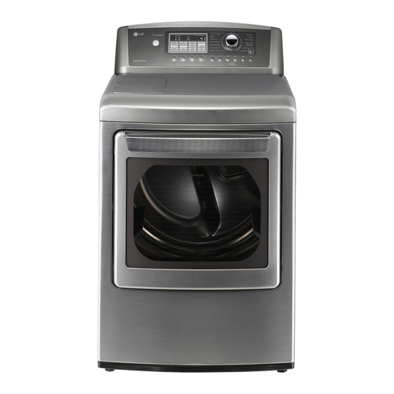
ELECTRIC & GAS DRYER
SERVICE MANUAL
CAUTION
READ THIS MANUAL CAREFULLY IN ORDER TO
PROPERLY DIAGNOSE PROBLEMS AND TO SAFELY
PROVIDE QUALITY SERVICE ON THESE DRYERS.
MODEL : DLEX5101W
DLEX5101V
DLEX5170W
DLEX5170V
U.S.A. Website: http://us.lgservice.com
Canadian Website: http://lg.ca
DLGX5102W
DLGX5102V
DLGX5171W
DLGX5171V
Advertisement
Table of Contents
Troubleshooting

Summarization of Contents
IMPORTANT SAFETY NOTICE
Electrostatic Discharge (ESD) Sensitive Electronics
Procedures to prevent damage from electrostatic discharge to electronic components.
SPECIFICATIONS
ACCESSORIES
Lists available accessories for the dryer model.
INSTALLATION INSTRUCTIONS
Dryer Rack Installation
Step-by-step guide for installing the dryer rack.
Electrical Connection Options
Instructions for connecting 3-wire and 4-wire power supplies.
Gas Supply Pipe Connection
Detailed instructions for connecting the gas supply pipe to the dryer.
STEAM FUNCTION
Steam Cycle Guide
Guide detailing steam cycle settings, time, and load capacity.
Troubleshooting for Steam Dryer
Common problems and solutions specific to steam dryer functions.
Display Fault/Error Codes for Steam Dryer
Lists error codes for steam dryer operation and their meanings.
FLOW SENSOR FUNCTION
Flow Sensor Functionality
Explanation of the FlowSense™ function for detecting duct blockages.
Installation Check Procedure
Procedure to check exhaust system adequacy after installation.
Flow Sensor Troubleshooting
Solutions for issues related to the flow sensor indicator light.
DIAGNOSTIC TEST
Test 1: 120V AC Electrical Supply
Procedure to test the 120V AC electrical supply to the dryer.
Tab Relay Connections and Errors
Details on tab relay power connections, status modes, and error results.
Test 2: Thermistor Test
Procedure to test thermistors by measuring resistance with power off.
Test 3: Motor Test
Procedure to test the motor by measuring resistance.
Test 4: Moisture Sensor
Procedure to test the moisture sensor by measuring resistance and voltage.
Test 5: Door Switch Test
Procedure to test the door switch by measuring resistance.
Test 6: Heater Switch Test
Procedure to test heater switches for electric dryers.
Test 7: Gas Valve Test
Procedure to test gas valves for gas dryers.
Test 8: Motor Assembly, DC, Pump
Procedure to test the DC pump during diagnostic tests.
Test 9: Generator Assembly
Procedure to test the generator assembly for heating issues.
DISASSEMBLY INSTRUCTIONS
Control Panel and Rear Assembly
Steps for disassembling the control panel, rear panel, and top cover.
Cabinet and Frame Disassembly
Instructions for disassembling the cabinet, frame body, lid, and guide assembly.
Drum and Lamp Component Removal
Procedures for removing the drum assembly and changing the drum lamp.
EXPLODED VIEW
Control Panel & Plate Assembly
Exploded view of the control panel and associated plates.
Guide Assembly
Exploded view of the guide assembly components.
Cabinet and Door Assembly: Gas Type
Exploded view of the cabinet and door assembly for gas models.
Drum and Motor Assembly: Gas Type
Exploded view of the drum and motor assembly for gas models.


Need help?
Do you have a question about the DLGX5171W and is the answer not in the manual?
Questions and answers