Advertisement
Quick Links
Download this manual
See also:
Instruction Manual
CD RECEIVER
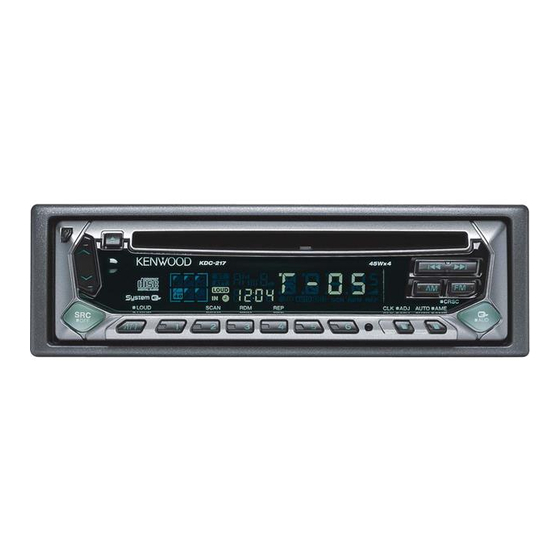
KDC-2019/2019V/217/217S
/219/29MR
/2020/3020/4020
SERVICE MANUAL
The CD mechanism infomation is not in this sarvice manual.
Please, refer to sarvice manual X92-4030-0x (B51-7867-00).
Panel assy
(A64-2544-02): KDC-219
(A64-2545-02): KDC-2019
(A64-2546-02): KDC-29MR
OFF
Panel assy
(A64-2566-02): KDC-217
(A64-2695-02): KDC-217S
OFF
∗
DC cord
(E30-4783-05)
(E30-4784-05)
Mounting hardware assy
(J21-9641-13)
∗
Depends on the model. Refer to the parts list.
(A64-2547-02): KDC-2020
(A64-2548-02): KDC-4020
(A64-2680-02): KDC-3020
(A64-2711-02): KDC-2019V
CD MD-Changer Control
KDC-XXXX
COMPACT
DIGITAL AUDIO
LOUD
SCAN
RDM
REP
KDC-XXXX
COMPACT
DIGITAL AUDIO
LOUD
SCAN
RDM
REP
Plastic cabinet assy
(A02-1486-13)
Lever
(D10-4589-04)x2
© 2001-12 PRINTED IN JAPAN
B51-7874-00 ( N ) 1754
CD mechanism extension cord : W05-0618-00
Escutcheon
(B07-3054-02): KDC-2019/2019V
KDC-219/2020
(B07-3055-02): KDC-29MR
KDC-3020/4020
CRSC
CLK
ADJ
AUTO
AME
M. RDM
AUD
Escutcheon
(B07-3054-02): KDC-217/217S
CRSC
CLK
ADJ
AUTO
AME
AUD
∗
Remote controller assy
(A70-2024-05)
Screw set
(N99-1719-05)
∗
Stay
(J54-0606-04)
∗
Screw set
(N99-1610-15)
Advertisement

Summarization of Contents
Service Manual Overview and Part Identification
Panel Assemblies and Escutcheons
Lists and illustrates panel assemblies and escutcheons for various models.
Associated Service Accessories
Shows common accessories included for service, such as cords and screws.
System Block Diagram
Component Interconnection Overview
Illustrates the overall system architecture and component interactions.
Microcomputer Terminal Descriptions
IC1 Pinout and Terminal Functions
Details the pin assignments, I/O, and purpose of the microcomputer's terminals.
Microcomputer and Adjustment Procedures
IC1 Terminal Details (Continued)
Continues the pinout and function description for the microcomputer IC1.
Tuning and Adjustment Settings
Outlines input settings and alignment points for FM and AM tuner sections.
Printed Circuit Board Layouts
PC Board Component Side View
Shows the component placement on the PC board.
PC Board Foil Side View
Displays the copper traces and connections on the PC board.
Schematic Diagram
Detailed Circuit Schematics
Presents the complete circuit diagram for the device.
Component Identification and Safety
Component Details and Model Compatibility
Lists specific components and their application across different models.
Critical Safety Warnings
Provides essential safety warnings and guidelines for handling the unit.
Switch Unit and Component Cross-Reference
Switch Unit Diagrams and Connections
Illustrates the switch units and their respective connections.
Component Compatibility by Model
Details component compatibility across various product models.
Exploded View for Assembly
Unit Disassembly and Reassembly Guide
Provides an exploded view illustrating the unit's construction and assembly process.
Comprehensive Parts List
General Parts Inventory
Lists all service parts with their corresponding part numbers and descriptions.
Electric Unit Parts List (Continued)
Electric Unit Components (ICs, Diodes, Capacitors)
Details parts specific to the electric unit, including ICs, diodes, and capacitors.
Electric Unit Components List
Resistors, Coils, and Connectors
Lists resistors, coils, connectors, and their specifications for the electric unit.
Electric Unit Components (Diodes and Transistors)
Diodes, ICs, and Transistors
Details diodes, integrated circuits, and transistors used in the electric unit.
Product Specifications
FM, AM, and CD Performance Metrics
Details FM, AM, and CD performance parameters for K-type and M-type models.
Amplifier and General Operating Specs
Outlines amplifier, tone, and general operating specifications for the units.


Need help?
Do you have a question about the KDC-4020 and is the answer not in the manual?
Questions and answers