Table of Contents
Advertisement
QQ
3 7 63 1515 0
SERVICE MANUAL
Ver 1.0 2000. 03
TE
L 13942296513
CD player section
System
Compact disc digital audio system
Laser diode properties
Material: GaAlAs
Wave length: 780 nm
Emission duration: Continuous
Laser output: Less than 44.6 µW
(This output is the value measured at a distance of
about 200 mm from the objective lens surface on
the optical pick-up block with 7 mm aperture.)
Spindle speed
200 r/min (rpm) to 500 r/min (rpm) (CLV)
Number of channels
2
Frequency response
20 - 20,000 Hz +1/–2 dB
Wow and flutter
Below measurable limit
Radio section
Frequency range
CFD-S22L/S32L
FM
MW
LW
IF
FM: 10.7 MHz
MW/LW: 450 kHz
Aerials
FM: Telescopic aerial
MW/LW: Built-in ferrite bar aerial
www
.
http://www.xiaoyu163.com
CFD-S22L/S32L
87.5 - 108 MHz
531 - 1,602 kHz
531 - 279 kHz
x
ao
y
i
http://www.xiaoyu163.com
8
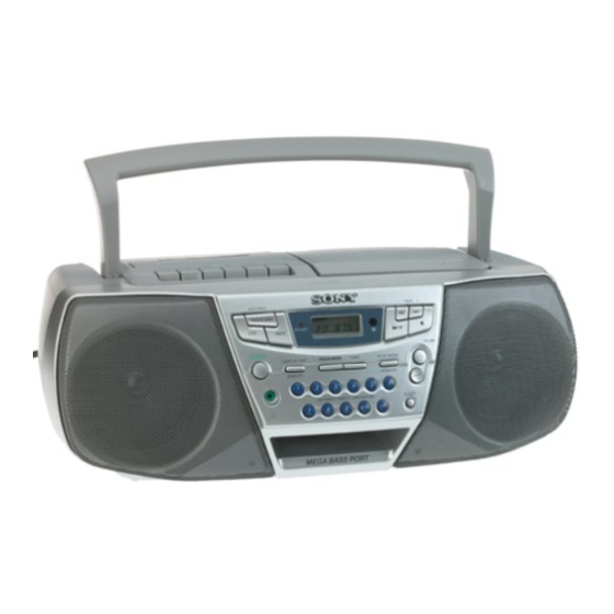
Photo: CFD-S32L
Model Name Using Similar Mechanism CFD-S38L
CD
CD Mechanism Type
Section
Optical Pick-up Name
Model Name Using Similar Mechanism CFD-S38L
TC
Section Tape Transport Mechanism Type
Q Q
3
6 7
1 3
SPECIFICATIONS
Cassette-corder section
Recording system
4-track 2 channel stereo
Fast winding time
Approx. 120 sec. with Sony cassette C-60
Frequency response
TYPE I (normal): 70 - 10,000 Hz
General
Speaker
Full range: 10 cm (4 in.) dia.,
3.2 ohms, cone type (2)
Outputs
Headphones jack (stereo minijack)
For 16 - 68 ohms impedance headphones
Maximum power output
2.3 W + 2.3 W
Power requirements
For CD radio cassette-corder:
230 V AC, 50 Hz
9 V DC, 6 R20 (size D) batteries
For remote control (CFD-S32L only):
3 V DC, 2 R6 (size AA) batteries
Power consumption
AC 20 W
CD RADIO CASSETTE-CORDER
u163
.
– 1 –
2 9
9 4
2 8
AEP Model
1 5
0 5
8
2 9
9 4
– Continued on next page –
m
co
9 9
UK Model
KSM-213CDM
KSS-213C
MF-S22-117
2 8
9 9
Advertisement
Table of Contents

Related Manuals for Sony CFD-S32L


Summarization of Contents
SECTION 1 SERVICING NOTES
Servicing Notes - Chuck Plate Jig
Procedure for using a jig to repair the CD section.
Servicing Notes - Laser Diode Check
Steps to check laser diode emission and focus search operation.
SECTION 2 GENERAL
Location of Controls
Identifies controls on the player and remote.
Sound Emphasis Adjustment
How to adjust bass and tone settings for enhanced sound.
SECTION 3 DISASSEMBLY
Cabinet (Front) Sub Assy
Exploded view and parts for the front cabinet section.
Internal Boards Disassembly
Exploded views for wires, secondary, and power boards.
Internal Boards Disassembly
Exploded views for tuner board and upper cabinet block.
Mechanisms and Boards Disassembly
Exploded views for main board and CD mechanism block.
PRE Board Disassembly
Exploded view and parts for the PRE board.
SECTION 4 MECHANICAL ADJUSTMENTS
Torque Measurement
Procedure and tools for measuring tape torque.
Tape Tension Measurement
Procedure for measuring tape tension.
SECTION 5 ELECTRICAL ADJUSTMENTS
Tape Section Adjustments
Electrical adjustments for the tape playback system.
Tuner Section Adjustments
Adjustments for radio reception (FM, MW, LW) frequency and tracking.
CD Section Focus Bias Check
Procedure to check focus bias using an oscilloscope.
SECTION 6 DIAGRAMS
IC Pin Description
Pin assignments and functions for integrated circuits.
Circuit Boards Location
Diagram showing the location of various circuit boards.
Block Diagram – CD Section
Block diagram illustrating the CD section's signal flow.
Block Diagram – Main Section
Block diagram illustrating the main section's signal flow.
Printed Wiring Board – Tuner Section
Physical layout of components on the tuner section's PCB.
Schematic Diagram – Tuner Section
Electrical schematic of the tuner section.
Schematic Diagram – CD Section
Electrical schematic of the CD section.
Schematic Diagram – Control Section
Electrical schematic of the control section.
Schematic Diagram – Power Supply Section
Electrical schematic of the power supply section.
SECTION 7 EXPLODED VIEWS
Cabinet (Front) Section
Exploded view of the front cabinet section with parts list.
Cabinet (Rear) Section
Exploded view of the rear cabinet section with parts list.
Tape Mechanism Sections
Exploded view of the tape mechanism (part 1) with parts list.
Optical Pick-up Section
Exploded view of the optical pick-up section with parts list.
Need help?
Do you have a question about the CFD-S32L and is the answer not in the manual?
Questions and answers