Table of Contents
Advertisement
Quick Links
This manual has been provided for the use of authorized YAMAHA Retailers and their service personnel.
It has been assumed that basic service procedures inherent to the industry, and more specifically YAMAHA Products, are already
known and understood by the users, and have therefore not been restated.
WARNING:
IMPORTANT:
The data provided is believed to be accurate and applicable to the unit(s) indicated on the cover. The research, engineering, and
service departments of YAMAHA are continually striving to improve YAMAHA products. Modifications are, therefore, inevitable
and specifications are subject to change without notice or obligation to retrofit. Should any discrepancy appear to exist, please
contact the distributor's Service Division.
WARNING:
IMPORTANT:
I CONTENTS
To Service Personnel .......................................... 2
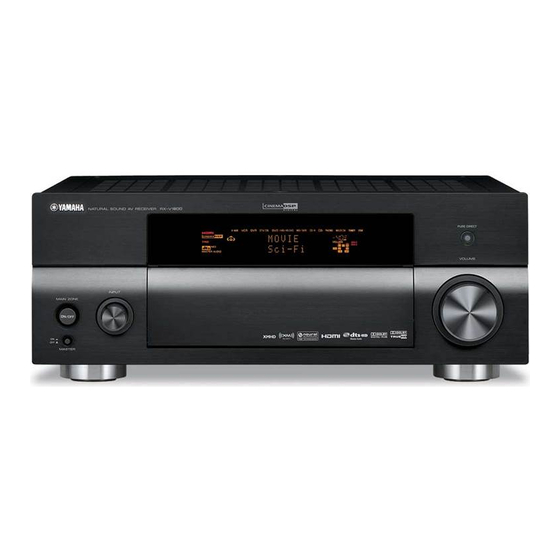
Front Panels ........................................................ 3–4
Rear Panels .......................................................... 5–8
Remote Control Panels ...................................... 9
Internal View ......................................................... 14
..................................... 20–33
1 0 1 0 6 3
AV RECEIVER/AV AMPLIFIER
RX-V1800/HTR-6190/
Failure to follow appropriate service and safety procedures when servicing this product may result in personal
injury, destruction of expensive components, and failure of the product to perform as specified. For these reasons,
we advise all YAMAHA product owners that any service required should be performed by an authorized
YAMAHA Retailer or the appointed service representative.
The presentation or sale of this manual to any individual or firm does not constitute authorization, certification or
recognition of any applicable technical capabilities, or establish a principle-agent relationship of any form.
Static discharges can destroy expensive components. Discharge any static electricity your body may have
accumulated by grounding yourself to the ground buss in the unit (heavy gauge black wires connect to this buss).
Turn the unit OFF during disassembly and part replacement. Recheck all work before you apply power to the unit.
................................ 10–13
.......... 14–20
34–70
2007
This manual is copyrighted by YAMAHA and may not be copied or
redistributed either in print or electronically without permission.
DSP-AX1800
SERVICE MANUAL
IMPORTANT NOTICE
Display Data ........................................................... 72
Ic Data ................................................................. 73–84
Block Diagrams .............................................. 85–87
Printed Circuit Boards .............................. 88–115
Pin Connection Diagrams ........................ 116–118
Schematic Diagrams .................................. 119–137
Replacement Parts List .......................... 139–174
REMOTE CONTROL .......................................... 175–178
All rights reserved.
71
179–181
P.O.Box 1, Hamamatsu, Japan
'07.08
Advertisement
Table of Contents

Related Manuals for Yamaha DSP-AX1800


Summarization of Contents
Service Manual Overview
Important Service Notice
Provides critical information for authorized service personnel regarding safety and procedures.
To Service Personnel
Critical Components Information
Highlights components with special characteristics requiring exact specification replacement.
Leakage Current Measurement
Verification procedure ensuring exposed conductive surfaces are insulated from supply circuits.
Chemical Content Notice
Warning about lead and other chemical traces in components and solder used in the product.
Specifications
Audio Section Specifications
Detailed technical data for the audio amplifier section, including power output and frequency response.
Video Section Specifications
Technical data for video inputs and outputs, including signal levels and impedance.
Internal View
Internal Unit Layout
Diagrams showing the top, front, and rear views of internal components and their locations.
Disassembly Procedures
Top Cover Removal
Step-by-step instructions for safely removing the top cover of the unit.
Front Panel Removal
Instructions for removing the front panel assembly from the unit.
Sub Chassis Unit Removal
Procedure for removing the sub chassis unit, including cable disconnections.
Updating Firmware
Firmware Update Methods
Describes three methods for updating firmware: using CD, PC (RS232C), or USER mode.
Self-Diagnostic Function
Diagnostic Menu Overview
Details the available menu items and sub-menu items for self-diagnostic testing.
Amp Adjustment
Idling Current Confirmation
Procedure to confirm and adjust the idling current of the amplifier unit.
Display Data
Pin Connections
Diagrams showing pin connections for various connectors on the PCB.
Grid Assignments
Layout of the pattern area grid, assigning numbers to specific pins.
IC Data
IC182 Microprocessor Pinout
Detailed pinout diagram and function description for the M30845MW microprocessor.
Block Diagrams
Audio Section Block Diagram
Illustrates the signal flow within the audio processing section of the unit.
Video Section Block Diagram
Illustrates the signal flow within the video processing section of the unit.
Printed Circuit Boards
DSP P.C.B. Layout
Component layout diagram for the DSP Printed Circuit Board (Side A).
Pin Connection Diagrams
Integrated Circuit (IC) Pinouts
Diagrams showing pin connections for various integrated circuits used in the unit.
Schematic Diagrams
DSP Section Schematics
Detailed circuit diagrams for the DSP section of the unit, covering multiple pages.
Replacement Parts List
Electrical Component Parts
List of electrical components with part numbers, descriptions, and specifications.
Service Warnings
Important warnings and cautions for service personnel regarding component handling and replacement.
Overall Assembly
Exploded Views
Diagrams showing the assembly of major units and their components.
Remote Control
Remote Control Layouts
Diagrams showing the button layout for different remote control models.
Key Codes
Table detailing the key codes and their corresponding functions for remote controls.
Advanced Setup
Advanced Setup Menu Guide
Instructions for accessing and navigating the advanced setup menu for configuration.
Need help?
Do you have a question about the DSP-AX1800 and is the answer not in the manual?
Questions and answers