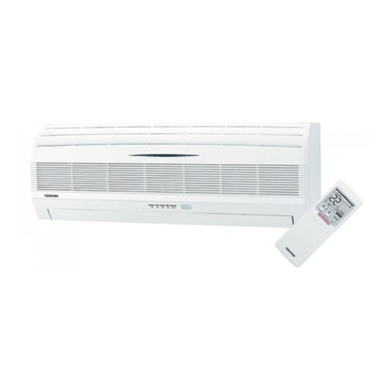
Table of Contents
Troubleshooting

Summarization of Contents
2. CONSTRUCTION VIEWS
2-1. Indoor Unit
Views and dimensions of the indoor unit.
2-2. Outdoor Unit (RAS-13UAH-ES4, RAS-10UAH-ES4, RAS-13UA-ES4, RAS-10UA-ES4)
Diagrams of outdoor units for specific models.
2-3. Outdoor Unit (RAS-07UA-ES4)
Diagrams of the RAS-07UA-ES4 outdoor unit.
3. WIRING DIAGRAM
3-1. RAS-13UKHP-ES4 / RAS-13UAH-ES4
Wiring diagram for specific indoor/outdoor unit models.
3-2. RAS-13UKP-ES4 / RAS-13UA-ES4
Wiring diagram for specific indoor/outdoor unit models.
3-3. RAS-13UKP-ES4 / RAS-10UA-ES4
Wiring diagram for specific indoor/outdoor unit models.
3-4. RAS-10UKP-ES4 / RAS-10UA-ES4
Wiring diagram for specific indoor/outdoor unit models.
3-5. RAS-07UKP-ES4 / RAS-07UA-ES4
Wiring diagram for specific indoor/outdoor unit models.
4. SPECIFICATION OF ELECTRICAL PARTS
4-1. Indoor Unit (RAS-13UKHP-ES4, RAS-10UKHP-ES4)
Electrical component specs for specific indoor units.
4-2. Outdoor Unit (RAS-13UAH-ES4)
Electrical component specs for RAS-13UAH-ES4 outdoor unit.
4-3. Outdoor Unit (RAS-13UA-ES4)
Electrical component specs for RAS-13UA-ES4 outdoor unit.
4-4. Outdoor Unit (RAS-10UAH-ES4)
Electrical component specs for RAS-10UAH-ES4 outdoor unit.
4-5. Indoor Unit (RAS-13UKP-ES4, RAS-10UKP-ES4, RAS-07UKP-ES4)
Electrical component specs for specific indoor units.
4-6. Outdoor Unit (RAS-10UA-ES4)
Electrical component specs for RAS-10UA-ES4 outdoor unit.
4-7. Outdoor Unit (RAS-07UA-ES4)
Electrical component specs for RAS-07UA-ES4 outdoor unit.
5. REFRIGERATION CYCLE DIAGRAM
5-1. RAS-13UKHP-ES4/ RAS-13UAH-ES4
Refrigeration cycle diagram for specific model pairs.
5-2. RAS-10UKHP-ES4 / RAS-10UAH-ES4
Refrigeration cycle diagram for specific model pairs.
5-3. RAS-13UKP-ES4 / RAS-13UA-ES4
Refrigeration cycle diagram for specific model pairs.
5-4. RAS-10UKP-ES4 / RAS-10UA-ES4
Refrigeration cycle diagram for specific model pairs.
5-5. RAS-07UKP-ES4 / RAS-07UA-ES4
Refrigeration cycle diagram for specific model pairs.
6. CONTROL BLOCK DIAGRAM
6-1. RAS-13UKHP-ES4 / RAS-13UAH-ES4, RAS-10UKHP-ES4 / RAS-10UAH-ES4
Control block diagram for specific indoor/outdoor units.
6-2. RAS-13UKP-ES4 / RAS-13UA-ES4, RAS-10UKP-ES4 / RAS-10UA-ES4, RAS-07UKP-ES4 / RAS-07UA-ES4
Control block diagram for multiple specific indoor/outdoor units.
7. OPERATION DESCRIPTION
7-1. Outline of Air Conditioner Control
Overview of how the air conditioner is controlled.
7-2. Description of Operation Circuit
Details on operational states like fan-only, cooling, dry, heating.
7-3. Hi POWER Mode
Explanation of the Hi POWER mode operation.
7-4. High-Temperature Limit Control
Control to prevent excessive indoor heat exchanger temperature.
7-5. Low-Temperature Limit Control
Control to prevent indoor heat exchanger freezing.
7-6. Defrost Operation *Heat pump model only
Process of defrosting the outdoor unit during heating.
7-7. Current Limit Control *Heat pump model only
Control to prevent exceeding current limits.
7-8. Auto Restart Function
How the unit automatically restarts after power interruption.
7-9. Filter Check Lamp
Information about the filter check indicator and reset.
7-10. Self-Cleaning function
Function to reduce humidity and prevent mold.
7-11. QUIET Mode
Operation mode for reduced noise and fan speed.
7-12. COMFORT SLEEP mode
Mode for comfortable sleep with auto temp adjustment.
8. INSTALLATION PROCEDURE
8-1 Safety Cautions
Crucial safety guidelines for installation. Covers public and new refrigerant.
8-2 Installation Diagram of Indoor and Outdoor Units
Visual guides for placing and connecting units.
8-3 Installation
General installation steps and optional parts.
8-4 Indoor Unit
Guidelines for installing the indoor unit.
8-5 Outdoor Unit
Guidelines for installing the outdoor unit.
8-6 How to Set Remote Control Selector Switch
Setting the remote control selector for multi-unit installations.
8-7 Others
Miscellaneous installation-related topics.
9. TROUBLESHOOTING CHART
9-1 Troubleshooting Procedure
Step-by-step guide to diagnose and resolve issues.
9-2 Basic Check Items
Initial checks for power supply and connections.
9-3 Primary Judgement
Diagnosing issues based on symptoms and controller roles.
9-4 Self-Diagnosis by Remote Control (Check Code)
Using remote control for fault code diagnosis.
9-5 Troubleshooting Flowcharts
Visual flowcharts for diagnosing operational problems.
9-6 Troubleshooting for Remote Control (Including The Indoor P.C. Board)
Diagnosing remote control and PC board issues.
10. PARTS REPLACEMENT
10-1 Indoor Unit
Procedures for replacing components in the indoor unit.
10-2 Outdoor Unit
Procedures for replacing components in the outdoor unit.
11. EXPLODED VIEWS AND PARTS LIST
11-1 Indoor Unit (E-Parts Assy) (For Heat pump model)
Exploded view and parts list for indoor unit heat pump models.
11-2 Indoor Unit (E-Parts Assy) (For Cooling model)
Exploded view and parts list for indoor unit cooling models.
11-3 Indoor Unit
Exploded view and parts list for indoor unit components.
11-4 Outdoor Unit (RAS-13UAH-ES4)
Exploded view and parts list for RAS-13UAH-ES4 outdoor unit.
11-5 Outdoor Unit (RAS-10UAH-ES4)
Exploded view and parts list for RAS-10UAH-ES4 outdoor unit.
11-6 Outdoor Unit (RAS-13UA-ES4)
Exploded view and parts list for RAS-13UA-ES4 outdoor unit.
11-7 Outdoor Unit (RAS-10UA-ES4)
Exploded view and parts list for RAS-10UA-ES4 outdoor unit.
11-8 Outdoor Unit (RAS-07UA-ES4)
Exploded view and parts list for RAS-07UA-ES4 outdoor unit.


Need help?
Do you have a question about the RAS-13UA-ES4 and is the answer not in the manual?
Questions and answers