Table of Contents
Advertisement
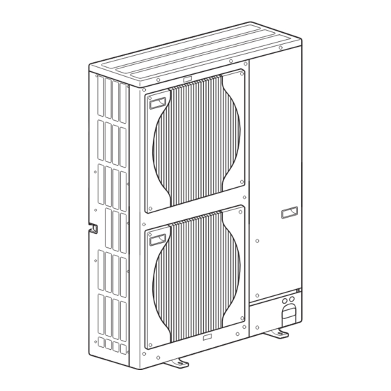
SPLIT-TYPE, HEAT PUMP AIR CONDITIONERS
SERVICE MANUAL
R410A
Outdoor unit
[Model Name]
PUHZ-SHW80VHA
PUHZ-SHW112VHA
PUHZ-SHW112YHA
PUHZ-SHW140YHA
Salt proof model
PUHZ-SHW80VHA-BS
PUHZ-SHW112VHA-BS
PUHZ-SHW112YHA-BS
PUHZ-SHW140YHA-BS
[Service Ref.]
PUHZ-SHW80VHA
PUHZ-SHW80VHAR2.UK
PUHZ-SHW112VHA
PUHZ-SHW112VHAR2.UK
PUHZ-SHW112YHA
PUHZ-SHW112YHAR1
PUHZ-SHW112YHAR2.UK
PUHZ-SHW140YHA
PUHZ-SHW140YHAR1
PUHZ-SHW140YHAR2.UK
PUHZ-SHW80VHAR2-BS.UK
PUHZ-SHW112VHAR2-BS.UK
PUHZ-SHW112YHAR2-BS.UK
PUHZ-SHW140YHAR2-BS.UK
REVISED EDITION-B
Revision:
• Added
PUHZ-SHW80/112VHAR2(-BS).UK
and
PUHZ-SHW112/140YHAR2(-BS).UK
in REVISED EDITION-B.
• Some descriptions have been
modified.
• Please void OCH526 REVISED
EDITION-A.
Note:
• This manual describes service data
of the outdoor units only.
• RoHS compliant products have
<G> mark on the spec name plate.
CONTENTS
1. TECHNICAL CHANGES ······························· 2
2. REFERENCE MANUAL ································ 2
3. SAFETY PRECAUTION ······························· 3
4. SPECIFICATIONS ········································ 7
5. DATA ····························································· 9
6. OUTLINES AND DIMENSIONS·················· 10
7. WIRING DIAGRAM ····································· 12
8. WIRING SPECIFICATIONS ························ 17
9. REFRIGERANT SYSTEM DIAGRAM ········ 18
10. TROUBLESHOOTING ································ 20
11. FUNCTION SETTING ································· 82
12. MONITORING THE OPERATION DATA BY THE REMOTE CONTROLLER ···· 95
13. EASY MAINTENANCE FUNCTION ········· 106
14. DISASSEMBLY PROCEDURE ················· 113
PARTS CATALOG (OCB526B)
December 2013
No.OCH526
Advertisement
Table of Contents
Troubleshooting

Related Manuals for Mitsubishi Mr.Slim PUHZ-SHW112YHA


Summarization of Contents
REFERENCE MANUAL
2-1. FOR AIR TO WATER SYSTEM
Lists models and their corresponding service manual numbers.
2-2. FOR AIR TO AIR SYSTEM
Lists models and their corresponding service manual numbers.
SAFETY PRECAUTION
3-1. ALWAYS OBSERVE FOR SAFETY
General safety rules before and during repair services.
3-2. CAUTIONS RELATED TO NEW REFRIGERANT
Specific safety advice for R410A refrigerant.
PRECAUTIONS WHEN REUSING EXISTING R22 REFRIGERANT PIPES
(1) Flowchart
Visual guide for determining if existing R22 pipes can be reused.
Cautions for refrigerant piping work
1 Thickness of pipes
Specifies required pipe thickness for R410A refrigerant.
2 Dimensions of flare cutting and flare nut
Details on flare cutting and nut dimensions for R410A.
3 Tools for R410A
Lists necessary tools and their compatibility with R410A and R22.
DATA
5-1. REFILLING REFRIGERANT CHARGE (R410A: kg)
Table showing refrigerant charge amounts based on piping length.
5-2. COMPRESSOR TECHNICAL DATA
Technical specifications for compressor models.
5-3. NOISE CRITERION CURVES
Graphical representation of noise levels for different operating modes.
OUTLINES AND DIMENSIONS
Unit Installation Clearances and Space Requirements
Recommended clearances for unit installation and service access.
Foundation Bolts and Piping/Wiring Directions
Information on foundation bolts, piping, and wiring connections.
WIRING SPECIFICATIONS
FIELD ELECTRICAL WIRING Specifications
Details on power supply, wire sizes, and circuit ratings for outdoor units.
Refrigerant Handling and Operation Procedures
9-1. REFRIGERANT COLLECTING (PUMP DOWN)
Procedure for safely collecting refrigerant before unit removal or disposal.
9-2. UNIT REPLACEMENT OPERATION
Specific steps for replacing units with existing R22 refrigerant pipes.
9-3. START AND FINISH OF TEST RUN
Essential steps for commissioning and verifying unit operation.
TROUBLESHOOTING
10-1. TROUBLESHOOTING Summary
General guidance on error code display and actions.
10-2. CHECK POINT UNDER TEST RUN
Pre-test run checks to ensure proper installation and safety.
Test Run Procedures for Wired Remote Controllers
10-2-2. Test run for wired remote controller
Step-by-step guide for performing test runs using a specific remote controller.
Test Run for Wired Remote Controller
10-2-3. Test Run for Wired Remote Controller
Guide for test runs using a different remote controller model.
Test Run for Wireless Remote Controller
10-2-4. Test Run for Wireless Remote Controller
Procedure for performing test runs using a wireless remote controller.
HOW TO PROCEED "SELF-DIAGNOSIS"
10-3-1. Self-Diagnosis with PAR-31MAA Remote
Detailed steps for self-diagnosis using a specific remote controller.
Remote Controller Check with PAR-31MAA
10-3-2. Remote Controller Check with PAR-31MAA
Procedure to diagnose the remote controller's functionality.
Self-Diagnosis Procedures
10-3-3. Self-Diagnosis with PAR-21MAA Remote
Self-diagnosis procedure for a different remote controller model.
10-3-4. Maintenance Self-Diagnosis with PAR-21MAA
Self-diagnosis during maintenance or service operations.
Remote Controller Check with PAR-21MAA
10-3-5. Remote Controller Check with PAR-21MAA
Troubleshooting remote controller issues with a specific model.
Self-Diagnosis for Wireless Remote Controller
10-3-6. Self-diagnosis
Self-diagnosis procedure for wireless remote controllers.
Indoor and Outdoor Unit Error Patterns
[Output pattern A] Errors detected by indoor unit
Lists error codes and symptoms for indoor unit issues.
[Output pattern B] Errors detected by unit other than indoor unit (outdoor unit, etc.)
Lists error codes and symptoms for outdoor unit issues.
TROUBLESHOOTING OF PROBLEMS
Remote Controller Display Malfunctions
Troubleshooting steps for blank or intermittent remote controller displays.
Unit Operation Issues
Troubleshooting for unit startup, shutdown, and capacity problems.
Wireless Remote Control and Capacity Issues
4. Even controlling by the wireless remote controller, no beep is heard and the unit does not start operating.
Troubleshooting wireless remote control issues where the unit doesn't start.
5. When operating by the wireless remote controller, beep sound is heard, however, unit does not start operating.
Troubleshooting wireless remote control issues when beep is heard but unit doesn't start.
6. Remote controller display works normally and the unit performs cooling operation, however, the capacity cannot be fully obtained. (The air does not cool well.).
Diagnosing reduced cooling capacity when the remote works normally.
Common Operational Phenomena and Troubleshooting
An error code appears in the remote controller display.
General guidance when an error code is displayed.
Unit does not operate at all.
Troubleshooting steps when the unit fails to operate at all.
Remote controller issues
Common remote controller problems and customer call scenarios.
Insufficient Cooling or Heating Performance
Diagnosing insufficient cooling or heating performance.
Blower Operation Issues
Troubleshooting problems related to the blower's operation and airflow.
Airflow Direction Control Issues
Troubleshooting problems with airflow direction control.
Unexpected Unit Operation
Diagnosing unexpected unit startup or shutdown events.
Remote Controller Display Issues
Troubleshooting dim, blank, or signal reception problems with remote controllers.
Troubleshooting "PLEASE WAIT" Display
Symptoms: “PLEASE WAIT” is kept being displayed on the remote controller
Flowchart for diagnosing persistent "PLEASE WAIT" display issues.
Troubleshooting Blank Remote Controller Display
Symptoms: Nothing is displayed on the remote controller
Flowchart for troubleshooting a blank remote controller display.
HOW TO CHECK THE PARTS
Thermistor and Coil Resistance Checks
Resistance values and checking procedures for thermistors, coils, motors, and valves.
Fan Motor and Compressor Checks
Procedures for checking fan motor and compressor motor components.
DC Fan Motor and Circuit Board Checks
Check method of DC fan motor (fan motor / outdoor controller circuit board)
Detailed steps to check DC fan motor and related circuit board.
Linear Expansion Valve Operation
Linear expansion valve
Operation summary and output pulse signals for linear expansion valves.
EMERGENCY OPERATION
(1) When the error codes shown below are displayed...
Conditions, cautions, and procedures for activating emergency operation.
(2) Check the following items and cautions for emergency operation
Important checks and warnings before using emergency operation.
(3) Emergency operation procedure
Step-by-step guide to activate emergency operation.
(4) Releasing emergency operation
Steps to disable emergency operation.
Emergency Operation Data
(5) Operation data during emergency operation
Data values displayed during emergency operation for cooling and heating.
FUNCTION OF SWITCHES, CONNECTORS AND JUMPERS
(1) Function of switches
Explains the function and settings of various DIP switches and push switches.
Switch and Connector Functions
(1) Function of switches (Continued)
Explains functions of SW5, SW7, SW9, SW6.
(2) Function of connector
Explains the function of CN31 connector for emergency operation.
Special function (Low-level sound priority & On-demand control)
Special function
Details on low-level sound priority mode and on-demand control wiring.
Indication of LED and Error Codes
Indication
Maps LED indicators and error codes to inspection methods.
SW2 setting for display interpretation
SW2 setting
Explains display details for various parameters based on SW2 settings.
SW2 Setting Display Details
SW2 setting (Continued)
Explains display details for various parameters based on SW2 settings.
SW2 Setting Display Details (Continued)
SW2 setting (Continued)
Explains display details for unit settings and temperatures based on SW2.
SW2 Setting Display Details (Continued)
SW2 setting (Continued)
Explains display details for discharge superheat, sub-cool, and error history based on SW2.
SW2 Setting Display Details (Continued)
SW2 setting (Continued)
Explains display details for DC bus voltage, capacity save, and error history based on SW2.
SW2 Setting Display Details (Continued)
SW2 setting (Continued)
Explains display details for LEV opening pulse, temperatures, and heatsink temp based on SW2.
SW2 Setting Display Details (Continued)
SW2 setting (Continued)
Explains display details for compressor operation status and pipe temperatures based on SW2.
SW2 Setting Display Details (Continued)
SW2 setting (Continued)
Explains display details for suction pipe temp, LEV/Comp surface temp, and U9 error details based on SW2.
FUNCTION SETTING
11-1. UNIT FUNCTION SETTING BY THE REMOTE CONTROLLER
How to set unit functions using the wired remote controller.
Function Availability by Unit Number
(2) Functions are available when setting the unit number to 01-03 or AL (07 in case of wireless remote controller)
Explains function availability based on unit numbers and system type.
Selecting functions using the wired remote controller
11-1-1. Selecting functions using the wired remote controller
Detailed guide for selecting functions via wired remote.
Selecting functions using the wired remote controller
11-1-2. Selecting functions using the wired remote controller
Detailed guide for selecting functions via wired remote.
Function Selection Operating Procedure
[Operating Procedure] for Function Selection
General operating procedure for function selection.
Selecting functions using the wireless remote controller
11-1-3. Selecting functions using the wireless remote controller (Type C)
Guide for selecting functions using a wireless remote controller.
FUNCTION SELECTION OF REMOTE CONTROLLER
11-2. FUNCTION SELECTION OF REMOTE CONTROLLER
Overview of remote controller functions and buttons.
11-2-1. PAR-31MAA
Detailed explanation of PAR-31MAA remote controller functions.
Setting Details for Various Menus
Setting details for Initial setting, Service, and Maintenance
Details for settings in Initial setting, Service, and Maintenance menus.
Remote Controller Function Selection Flowcharts
Item 1, 2, 3, 4 [Function selection flowchart]
Flowcharts for remote controller function selection procedures.
Function Selection Flowcharts (Detailed)
[Function selection flowchart]
Visual flow for changing language, function limits, mode, and display settings.
MONITORING THE OPERATION DATA BY THE REMOTE CONTROLLER
12-1. HOW TO "MONITOR THE OPERATION DATA"
Steps to monitor operation data using the remote controller.
12-1-1. PAR-31MAA
Guide for monitoring data with PAR-31MAA remote controller.
Monitoring Operation Data with PAR-21MAA
12-1-2. PAR-21MAA
Guide for monitoring data with PAR-21MAA remote controller.
Request Code Details: Operation, Control, and Frequency States
[Operation state] (Request code "0")
Details on operation states and relay output.
[Indoor unit – Control state] (Request code "50")
Details on indoor unit control states.
[Outdoor unit – Control state] (Request code "51")
Details on outdoor unit control states.
[Compressor – Frequency control state] (Request code "52")
Details on compressor frequency control states.
Request Code Details: Fan, Actuator, and Error Content
[Fan control state] (Request code "53")
Details on fan control states.
[Actuator output state] (Request code "54")
Details on actuator output states.
[Error content (U9)] (Request code "55")
Details on error content related to U9.
Request Code Details: Demand Capacity, External Inputs, and Unit Settings
[Contact demand capacity] (Request code "61")
Settings for contact demand capacity.
[External input state] (Request code "62")
Status of external inputs like silent mode.
[Outdoor unit - Capacity setting display] (Request code "70")
Display for outdoor unit capacity settings.
[Outdoor unit - Setting information] (Request code "71")
Information on outdoor unit switch settings.
Outdoor Unit Switch Setting Display
[Outdoor unit switch setting display (SW1 to SW10, except SW3)]
Mapping of DIP switch settings to data display and request codes.
Indoor Unit Setting Information
[Indoor unit – Model setting information] (Request code "162 ")
Setting information for indoor unit models.
[Indoor unit – Capacity setting information] (Request code "163")
Setting information for indoor unit capacity.
[Wireless pair No. (indoor control board side) setting] (Request code "165")
Setting for wireless pair numbers on indoor control boards.
EASY MAINTENANCE FUNCTION
13-1. SMOOTH MAINTENANCE
Procedure for smooth maintenance data display.
13-1-1. PAR-31MAA
Guide for smooth maintenance using PAR-31MAA remote.
MAINTENANCE MODE OPERATION METHOD
13-2. MAINTENANCE MODE OPERATION METHOD
How to switch to and operate maintenance mode.
● Switching to maintenance mode
Steps to activate maintenance mode.
Data measurement in Maintenance Mode
Data measurement
How to measure and display operation data.
INITIAL SETTINGS FOR REFRIGERANT LEAKAGE DETECTION FUNCTION
13-4-1. PAR-31MAA
Initial settings for refrigerant leakage detection using PAR-31MAA remote.
Initial Settings for Refrigerant Leakage Detection
13-4-2. PAR-21MAA
Initial settings for refrigerant leakage detection using PAR-21MAA remote.
Starting "Judgment of refrigerant leakage" Mode
3. How to start "Judgment of refrigerant leakage " mode.
Procedure to start refrigerant leakage judgment mode.
DISASSEMBLY PROCEDURE
1. Removing the service panel and top panel
Steps to remove the service and top panels.
2. Removing the fan motor (MF1, MF2)
Steps to remove the fan motor assembly.
3. Removing the electrical parts box
Steps to remove the electrical parts box.
Thermistor Removal Procedures
4. Removing the thermistor <2-phase pipe> (TH6) and thermistor (TH7)
Steps to remove 2-phase pipe and ambient thermistors.
5. Removing the thermistor (TH4) and thermistor (TH34)
Steps to remove discharge and surface thermistors.
6. Removing the thermistor (TH3), thermistor (TH32) and thermistor (TH33)
Steps to remove liquid, suction, and ref check thermistors.
Valve and Switch Removal Procedures
7. Removing the 4-way valve coil (21S4), and linear expansion valve coil (LEV-A, LEV-B, LEV-C)
Steps to remove 4-way valve and LEV coils.
8. Removing the 4-way valve
Steps to remove the 4-way valve assembly.
9. Removing linear expansion valve
Steps to remove the linear expansion valve.
10. Removing the high pressure switch (63H), the low pressure switch (63L) and the pressure sensor (63HS)
Steps to remove pressure switches and sensor.
Reactor and Compressor Removal
11. Removing the reactor (DCL) and capacitor (CB)
Steps to remove reactors and capacitors.
12. Removing the compressor (MC)
Steps to remove the compressor.
Power Receiver Removal
13. Removing the power receiver
Steps to remove the power receiver.
Disassembling the Electrical Parts Box
4. Disassembling the electrical parts box
Detailed steps for disassembling the electrical parts box.
Removing the Reactors
12. Removing the reactors (ACL1, ACL2, ACL3)
Steps to remove reactors.
Need help?
Do you have a question about the Mr.Slim PUHZ-SHW112YHA and is the answer not in the manual?
Questions and answers