Advertisement
Advertisement
Table of Contents

Related Manuals for Digital Design M2c


Summarization of Contents
Design Features
M-Class Design Features
Details design aspects of M-Class amplifiers, including stability, efficiency, protection, and adjustability.
SS-Class Design Features
Details design aspects of SS-Class amplifiers, including stability, efficiency, protection, circuitry, and compactness.
Controls and Connections
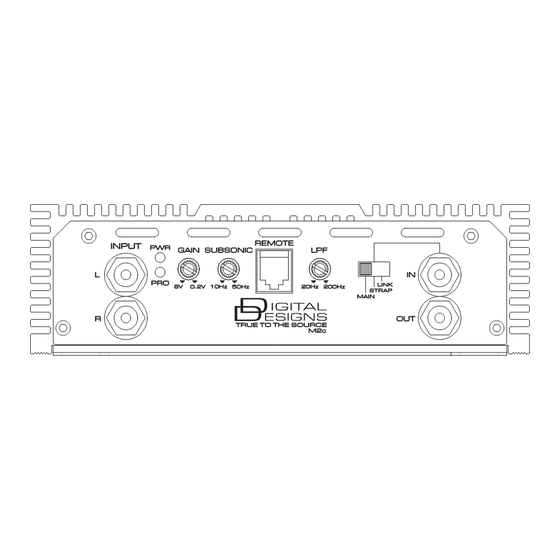
Control & Connection for Monoblock Amplifiers
Explains controls and connections for monoblock amplifiers, including input, power, gain, and indicators.
Remote Level Control Port
Describes the port for connecting a remote level control for adjusting amplifier output.
LPF Crossover Frequency Control
Explains the control for the low-pass filter crossover point for speaker outputs.
Main/Strap/Link Functionality
Details the function of Main/Strap/Link for connecting multiple amplifiers.
Remote Control Features
Describes the remote gain control, voltmeter, and clipping indicator features.
Ground Connection
Explains the ground connection requirements for the amplifier.
Power Connection
Details the power connection requirements, including battery terminal connection.
Speaker Output Terminals
Describes the speaker output terminals and impedance considerations.
Control & Connection for Multi-Channel Amplifiers
Explains controls and connections for full-range digital multi-channel amplifiers.
Input Signal Connection
Explains how to connect preamp signal cables to the amplifier's RCA input.
Output Signal Connection
Describes connecting the RCA output jack to another amplifier's input.
Gain Adjustment
Explains matching headunit output voltage to amplifier input.
High Pass Filter Control
Details the control for the high-pass filter point for speaker outputs.
HPF Crossover Selector
Determines if the amplifier operates in high-pass or full-range mode.
Low Pass Filter Control
Details the control for the low-pass filter point for speaker outputs.
LPF Crossover Selector
Determines if the amplifier operates in low-pass or full-range mode.
Power and Protection Indicators
Explains the Power LED and Protect LED indicators.
Installation Procedures
Mounting Preparation Steps
Steps to prepare for mounting, including disconnecting battery and checking connections.
Mounting Location Guidance
Guidance on selecting a mounting location for optimal heat dissipation and safety.
+12V, GND, REM Connection
Details the connection of power, ground, and remote turn-on wires.
Power Connection Details
Instructions for connecting the +12V power terminal, including fuse placement.
Ground Connection Instructions
Instructions for making a secure ground connection to the vehicle frame.
Remote Connection Procedure
Explains how to connect the remote turn-on cable to activate the amplifier.
M.80b, M1d & M2c Speaker Diagram I
Illustrates speaker connection for M.80b, M1d, M2c amplifiers (Diagram I).
M.80b, M1d & M2c Speaker Diagram II
Illustrates speaker connection for M.80b, M1d, M2c amplifiers (Diagram II).
SS2b & SS6 Speaker Diagram I
Illustrates speaker connection for SS2b and SS6 amplifiers (Diagram I).
SS2b & SS6 Speaker Diagram II
Illustrates speaker connection for SS2b and SS6 amplifiers (Diagram II).
SS4a Speaker Diagram I
Illustrates speaker connection for SS4a amplifier (Diagram I).
SS4a Speaker Diagram II
Illustrates speaker connection for SS4a amplifier (Diagram II).
SS4a Speaker Diagram III
Illustrates speaker connection for SS4a amplifier (Diagram III).
Daisy Chain Connection Guide
Instructions for linking multiple M.80b, M1d, M2c amplifiers together.
Main Amplifier in Daisy Chain
Details the role and connections of the main amplifier in a daisy chain.
Strap Amplifier in Daisy Chain
Details the role and connections of the strap amplifier in a daisy chain.
Multiple Connection (Main/Link Mode)
Instructions for linking multiple amplifiers using the Main/Link mode.
Main Amplifier Setup for Linking
Sets the main amplifier to the MAIN position for linking.
First Link Amplifier Connection
Connects the main amp output to the first link amp input.
Second Link Amplifier Connection
Connects the first link amp output to the second link amp input.
Troubleshooting Tips
No Sound or Output Issues
Troubleshooting steps for when the amplifier produces no sound or output.
Protection Mode Causes
Explains common protection modes and how to resolve them, including impedance and voltage.
Audio Distortion Problems
Troubleshooting steps for audio distortion issues.
Poor Bass Response Solutions
Troubleshooting steps for inadequate bass response from the amplifier.
Buzzing Sound Diagnosis
Troubleshooting steps for buzzing noise issues.
Whining Noise Resolution
Troubleshooting steps for whining noise, often related to engine noise.
Need help?
Do you have a question about the M2c and is the answer not in the manual?
Questions and answers