Sony Video Walkman GV-D900 Service Manual
Hide thumbs
Also See for Video Walkman GV-D900:
- Operating instructions manual (88 pages) ,
- Operating instructions manual (89 pages)
Table of Contents
Advertisement
GV-D300/D300E/D900/D900E
SERVICE MANUAL
Ver 1.0 1998.04
GV-D300/D900: NTSC
GV-D300E/D900E: PAL
Function difference table
Model
GV-D300/300E
Function
LCD
—
MICROFILM
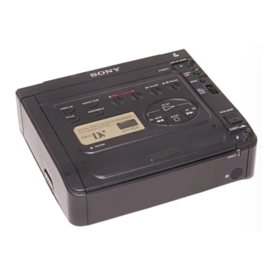
Photo: GV-D900E
For MECHANISM ADJUSTMENTS, refer to the "DV MECHANICAL
ADJUSTMENT MANUAL
supplement: 9-973-815-81) and "DV MECHANICAL ADJUSTMENT
MANUAL
GV-D900/D900E
5.5 inches
SPECIFICATIONS
DIGITAL VIDEO CASSETTE RECORDER
D MECHANISM " (original: 9-973-815-11),
D200 MECHANISM " (original: 9-973-981-11).
US Model
Canadian Model
GV-D300/D900
AEP Model
UK Model
E Model
GV-D300E/D900E
D200 MECHANISM
Advertisement
Table of Contents

Related Manuals for Sony Video Walkman GV-D900


Summarization of Contents
SERVICE NOTE
1. Power Supply During Repairs
Procedures to prevent power shut-off during repairs.
2. How to Take a Cassette Out When the Main Power Cannot Be Turned On (Forced Ejected)
Steps to eject a cassette when the unit is not powered on.
3. Warning Indicators
Explanation of warning lamp behavior and related error causes.
1. GENERAL
Using this manual
Guidance on how to use the service manual effectively.
Basic operations
Fundamental procedures like installing adapter and inserting cassette.
Advanced operations
Extended functionalities like editing, dubbing, and title creation.
Assemble editing
Step-by-step guide for performing assemble editing.
Usable cassettes and playback modes
Information on compatible cassettes and playback options.
Charging the vanadium-lithium battery in the VCR
Instructions for charging the internal lithium battery.
Maintenance information and precautions
Guidelines for proper care and handling to prevent damage.
Trouble check
Common issues and their corrective actions for troubleshooting.
Self-diagnosis display
Understanding the unit's self-diagnosis function and error codes.
Identifying the parts
Visual guide to locate and identify key components and controls.
Warning indicators
Explanation of various warning indicators and their meanings.
2. DISASSEMBLY
2-1. Cassette Lid Assembly
Procedure for removing the cassette lid assembly.
2-2. Cabinet (Bottom) Assembly, FP-571 (Lithium Battery)
Steps to remove the bottom cabinet and battery assembly.
2-3. MD Block Assembly, Battery Panel Assembly
Procedure for disassembling MD block and battery panel.
2-4. CB-61, RJ-77 Boards
Steps to remove CB-61 and RJ-77 circuit boards.
2-5. Control Switch Block (FK-71)
Procedure for removing the FK-71 control switch block.
2-6. MD Block
Steps for disassembling the MD block.
2-7. Cabinet (R) Assembly
Procedure for removing the right cabinet assembly.
2-8. IR-29, IO-62 Boards
Steps to remove the IR-29 and IO-62 circuit boards.
2-9. EX-34 Board
Procedure for removing the EX-34 circuit board.
2-10. Cabinet (Upper) Assembly
Steps to remove the upper cabinet assembly.
2-11. LCD Display Module (GV-D900/D900E)
Procedure for removing the LCD display module.
2-12. Circuit Boards Location
Diagram showing the location of various circuit boards.
3. BLOCK DIAGRAMS
3-1. Overall Block Diagram (1)
High-level functional block diagram of the unit's internal systems.
3-2. Overall Block Diagram (2)
Continuation of the high-level functional block diagram.
3-3. Power Block Diagram
Diagram illustrating the unit's power supply distribution and blocks.
4. PRINTED WIRING BOARDS AND SCHEMATIC DIAGRAMS
4-1. Frame Schematic Diagram
Overall schematic diagram of the unit's frame.
4-2. Printed Wiring Boards and Schematic Diagrams
Introduction to the detailed diagrams of printed wiring boards and schematics.
CB-61 (Chroma Process, SYNC SEP, SIG Interface, RGB Decoder, Audio, Mode Control, DC-DC Converter) Printed Wiring Board
Printed wiring board layout for the CB-61 board.
CB-61 (Video Input)(2/10) Schematic Diagram
Schematic diagram for the video input section of CB-61.
RJ-77 (REC/PB Process, RF Interface, Blocking, Mecha Con/Servo, Audio Signal Process, Mode Control) Printed Wiring Board
Printed wiring board layout for the RJ-77 board.
FP-242, FP-584 (Tape Sensors) Flexible Boards
Printed wiring boards for tape sensors.
EX-34 (DC-AC Inverter) Schematic Diagram
Schematic diagram for the EX-34 board's DC-AC inverter.
FK-71 (Control Switch Block) Printed Wiring Board
Printed wiring board layout for the FK-71 control switch block.
5. ADJUSTMENTS
5-1. Adjustment Preparations
Required tools and preparations before performing adjustments.
5-2. Mechanism Section Adjustment
Procedures for adjusting the mechanism section.
5-3. Electrical Adjustments
Detailed electrical adjustments for various systems.
5-4. Service Mode
How to enter and operate the service mode for adjustments.
6. REPAIR PARTS LIST
6-1. Exploded Views
Visual breakdown of the unit's assemblies with part numbers.
6-2. Electrical Parts List
Comprehensive list of electrical components with part numbers.
Need help?
Do you have a question about the Video Walkman GV-D900 and is the answer not in the manual?
Questions and answers