Sony GV-D1000E Service Manual
Hide thumbs
Also See for GV-D1000E:
- Operating instructions manual (220 pages) ,
- Limited warranty (1 page) ,
- Service manual (134 pages)
Table of Contents
Advertisement
Quick Links
SERVICE MANUAL
Ver 1.0 2002. 01
Revision History
Revision History
Link
Link
SPECIFICATIONS
SPECIFICATIONS
SERVICE NOTE
SERVICE NOTE
ORNAMENTAL PARTS
ORNAMENTAL PARTS
• For INSTRUCTION MANUAL, refer to separate file (992992972.pdf).
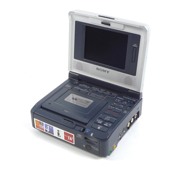
GV-D1000E
DISASSEMBLY
DISASSEMBLY
REPAIR PARTS LIST
REPAIR PARTS LIST
DIGITAL VIDEO CASSETTE RECORDER
RMT-811
1
LEVEL
AEP Model
UK Model
J200 MECHANISM
Advertisement
Table of Contents

Related Manuals for Sony GV-D1000E


Summary of Contents for Sony GV-D1000E
- Page 1 GV-D1000E RMT-811 SERVICE MANUAL LEVEL AEP Model Ver 1.0 2002. 01 UK Model Revision History Revision History J200 MECHANISM Link Link SPECIFICATIONS DISASSEMBLY SPECIFICATIONS DISASSEMBLY SERVICE NOTE REPAIR PARTS LIST SERVICE NOTE REPAIR PARTS LIST ORNAMENTAL PARTS ORNAMENTAL PARTS • For INSTRUCTION MANUAL, refer to separate file (992992972.pdf).
-
Page 2: Specifications
GV-D1000E COVER COVER SPECIFICATIONS AC power adaptor Input/output LCD screen connectors Picture Power requirements S video input System 10 cm (4.0 type) 100 - 240 V AC, 50/60 Hz 80.6 × 60.5 mm (3 1/4 × 2 1/2 in.) 4-pin mini DIN Video recording system Luminance signal: 1 Vp-p, 75 Ω... - Page 3 Danger of explosion if battery is incorrectly replaced. LIST ARE CRITICAL TO SAFE OPERATION. REPLACE THESE Replace only with the same or equivalent type. COMPONENTS WITH SONY PARTS WHOSE PART NUMBERS APPEAR AS SHOWN IN THIS MANUAL OR IN SUPPLEMENTS PUBLISHED BY SONY.
-
Page 4: Table Of Contents
GV-D1000E TABLE OF CONTENTS SERVICE NOTE POWER SUPPLY DURING REPAIRS ····························· 5 TO TAKE OUT A CASSETTE WHEN NOT EJECT (FORCE EJECT) ································································ 5 SELF-DIAGNOSIS FUNCTION SELF-DIAGNOSIS FUNCTION ······································· 6 SELF-DIAGNOSIS DISPLAY ·········································· 6 SERVICE MODE DISPLAY ············································· 6 3-1. Display Method ·································································· 6 3-2. -
Page 5: Service Note
GV-D1000E SERVICE NOTE COVER COVER POWER SUPPLY DURING REPAIRS In this unit, about 10 seconds after power is supplied (8.4V) to the battery terminal, the power is shut off so that the unit cannot operate. These following two methods are available to prevent this. Take note of which to use during repairs. -
Page 6: Self-Diagnosis Function
GV-D1000E SELF-DIAGNOSIS FUNCTION SELF-DIAGNOSIS FUNCTION SELF-DIAGNOSIS DISPLAY When problems occur while the unit is operating, the self-diagnosis When problems occur while the unit is operating, the counter of the function starts working, and displays on the LCD screen what to LCD screen shows a 4-digit display consisting of an alphabet and do. -
Page 7: Self-Diagnosis Code Table
GV-D1000E SELF-DIAGNOSIS CODE TABLE Self-diagnosis Code Block Detailed Symptom/State Correction Function Code Non-standard battery is used. Use the info LITHIUM battery. Condensation. Remove the cassette, and insert it again after one hour. Video head is dirty. Clean with the optional cleaning cassette. -
Page 8: Main Parts
GV-D1000E 1. MAIN PARTS COVER COVER Note: • Follow the disassembly procedure in the numerical order given. The components identified by mark 0 or • Items marked “*” are not stocked since they are seldom required for routine service. dotted line with mark 0 are critical for safety. -
Page 9: Disassembly
GV-D1000E COVER COVER DISASSEMBLY The following flow chart shows the disassembly procedure. 2-1. LCD cabinet assembly (See page 10) 2-2. PD-130 board, LS-56 board (See page 10) 2-3. LCD window cabinet assembly (LCD901, ND901, SP901, SP902) (See page 11) 2-4. Bottom cabinet assembly, FP-571 flexible board (V/L rechargeable battery) (See page 12) 2-5. -
Page 10: Lcd Cabinet Assembly
GV-D1000E NOTE: Follow the disassembly procedure in the numerical order given. 2-1. LCD CABINET ASSEMBLY 2 Two screws (M2 × 4), lock ace, p2 6 Remove the LCD cabinet assembly in the direction of the arrow. 3 Two screws (M2 × 3), lock ace, p2 1 Two screws (M2 ×... -
Page 11: Lcd Window Cabinet Assembly
GV-D1000E 2-3. LCD WINDOW CABINET ASSEMBLY (LCD901, ND901, SP901, SP902) 1 Two tapping screws (B2 × 6) 2 Two tapping screws (B2 × 6) 4 LCD ground plate 5 PD frame 3 Screw (M2 × 3), lock ace, p2 6 LCD901... -
Page 12: Bottom Cabinet Assembly, Fp-571 Flexible Board (V/L Rechargeable Battery)
GV-D1000E 2-4. BOTTOM CABINET ASSEMBLY, FP-571 FLEXIBLE BOARD (V/L RECHARGEABLE BATTERY) 7 Bottom cabinet assembly 4 Three MI screws 3 Three MI screws (M2 × 4) (H) (M2 × 4) (H) 6 Open the jack lid assembly in the direction of the arrow B. -
Page 13: Battery Terminal Board
GV-D1000E 2-6. BATTERY TERMINAL BOARD 3 Battery frame 5 Battery terminal board 4 Battery panel assembly 2 Two MI screws (M2 × 4) (H) 1 MI screw (M2 × 4) (H) 2-7. FP-575 FLEXIBLE BOARD (LANC), PR-41 BOARD, IO-69 BOARD 1 Three tapping screws qa Screw (M2 ×... -
Page 14: Board
GV-D1000E 2-8. MS-95 BOARD 3 Two FP-404 flexible boards (60P) 2 Two screws (M2 × 3), lock ace, p2 4 MS-95 board 1 FP-405 flexible board (10P) 2-9. MECHANISM DECK 1 Screw (M2 × 3), 2 Screw (M1.4 × 1.5) lock ace, p2 qa Three screws (M1.4 ×... -
Page 15: Board
GV-D1000E 2-10. EJ-35 BOARD 1 Two MI screws (M2 × 4) (H) 2 Cassette lid assembly 3 Press the cassette EJECT button in the direction of the arrow A and open the Lid frame assembly. 4 Four tapping screws (B2 × 6) -
Page 16: Board
GV-D1000E 2-11. EX-39 BOARD 1 Tapping screw (B2 × 6) 4 FP-570 flexible board 3 Lid lock assembly 9 EX-39 board 7 Two screws (M2 × 3), 8 EX frame lock ace, p2 2 Two MI screws (M2 × 4) (H) -
Page 17: Memory Stick Connector (10P)
GV-D1000E 2-12. MEMORY STICK CONNECTOR (10P), FK-81 BOARD 1 Three screws (M1.7 × 3), lock ace, p2 3 Memory stick connector (10P) 2 FP-405 flexible board (10P) 4 Four tapping screws (B2 × 6) 7 FK frame 8 FK-81 board 6 Three screws (M2 ×... -
Page 18: Fp-602 Flexible Board (Dv In/Out)
GV-D1000E 2-13. FP-602 FLEXIBLE BOARD (DV IN/OUT), LCD BLOCK ASSEMBLY 8 Hinge retainer bracket 4 Hinge retainer bracket 5 FP-602 flexible board 7 Two dowels (5P) 3 Two screws (M2 × 3), lock ace, p2 6 Two MI screws (M2 × 4) (H) 1 Two MI screws (M2 ×... -
Page 19: Hinge Unit, Fp-569 Flexible Board
GV-D1000E 2-14. HINGE UNIT, FP-569 FLEXIBLE BOARD When attaching the hinge unit, wrap the FP-569 flexible board hinge shaft as shown while taking care so that the flexible board must not be caught or pinched. Hinge unit FP-569 flexible board (26, 32P) -
Page 20: Repair Parts List
GV-D1000E COVER COVER REPAIR PARTS LIST 3-1. EXPLODED VIEWS NOTE: • -XX, -X mean standardized parts, so they may • The mechanical parts with no reference number The components identified by mark 0 or have some differences from the original one. -
Page 21: Cabinet (Upper) Section-1
GV-D1000E 3-1-2. CABINET (UPPER) SECTION-1 ns : not supplied LCD section (See page 23) Cabinet (upper) section-2 (See page 22) BT001 : BT001 (V/L rechargeable battary) FP-571 flexible board on the mount position. CAUTION : Danger of explosion if battery is incorrectly replaced. -
Page 22: Cabinet (Upper) Section-2
GV-D1000E 3-1-3. CABINET (UPPER) SECTION-2 ns : not supplied Ref. No. Part No. Description Ref. No. Part No. Description 3-945-884-11 SCREW (2X6) 3-072-563-01 FRAME, EX 3-072-564-01 FK FRAME not supplied EX-39 BOARD, COMPLETE not supplied FK-81 BOARD, COMPLETE 1-960-864-11 HARNESS (PL-53) -
Page 23: Lcd Section
GV-D1000E 3-1-4. LCD SECTION ns : not supplied ND901 SP901 LCD901 SP902 Ref. No. Part No. Description Ref. No. Part No. Description X-3952-180-1 CABINET ASSY, LCD WINDOW 1-960-864-11 HARNESS (PL-53) 3-064-405-01 PLATE, SP GROUND 3-064-404-01 BRACKET, LS 3-948-339-61 TAPPING not supplied... - Page 24 GV-D1000E 2002A1600-1 Sony EMCS Co. 9-929-929-41 ©2002.1 — 24 — Published by DI Customer Center...
- Page 25 Reverse 992992941.pdf Revision History S.M. Rev. Ver. Date History Contents issued 2002.01 Official Release — —...
Need help?
Do you have a question about the GV-D1000E and is the answer not in the manual?
Questions and answers