Table of Contents
Advertisement
Service
Manual
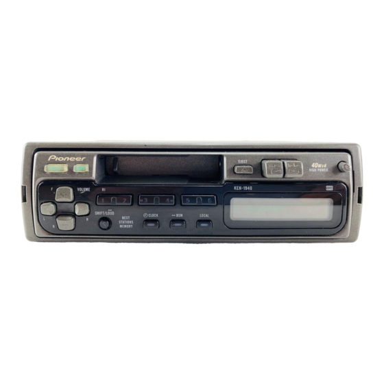
HIGH POWER CASSETTE PLAYER WITH FM/MW/LW TUNER
KEH-1940
KEH-1960
- This service manual should be used together with the following manual(s):
Model No.
Order No.
CX-644
CRT1800
CONTENTS
1. SAFETY INFORMATION............................................2
2. EXPLODED VIEWS AND PARTS LIST ......................2
4. PCB CONNECTION DIAGRAM................................20
5. ELECTRICAL PARTS LIST........................................28
6. ADJUSTMENT .........................................................32
PIONEER CORPORATION
PIONEER ELECTRONICS SERVICE INC.
PIONEER ELECTRONIC [EUROPE] N.V.
PIONEER ELECTRONICS ASIACENTRE PTE.LTD. 253 Alexandra Road, #04-01, Singapore 159936
C PIONEER CORPORATION 1999
KEH-1940/X1M/EW
X1M/EW
Mech. Module Remarks
2M
Cassette Mech. Module:Circuit Description, Mech.Description, Disassembly
4-1, Meguro 1-Chome, Meguro-ku, Tokyo 153-8654, Japan
P.O.Box 1760, Long Beach, CA 90801-1760 U.S.A.
Haven 1087 Keetberglaan 1, 9120 Melsele, Belgium
7. GENERAL INFORMATION.......................................34
7.1 DISASSEMBLY ..................................................34
7.2 PARTS ................................................................35
7.2.1 IC ...............................................................35
7.2.2 DISPLAY ...................................................38
8. OPERATIONS AND SPECIFICATIONS ....................39
K-ZZY. NOV. 1999 Printed in Japan
ORDER NO.
CRT2425
X1M/EW
Advertisement
Table of Contents

Related Manuals for Pioneer KEH-1960 X1W


Summarization of Contents
Exploded Views and Parts List
Packing Section Parts List
Details the components included in the product packaging.
Block Diagram and Schematic Diagram
Block Diagram
Illustrates the overall functional blocks of the tuner unit.
Overall Connection Diagram
Provides a guide to overall circuit connections.
FM/AM Tuner Unit Schematic
Details the schematic diagram for the FM/AM tuner.
PCB Connection Diagram
Tuner Amp Unit PCB Layout
Shows the component layout for the Tuner Amplifier PCB.
FM/AM Tuner Unit PCB Layout
Component layout for the FM/AM Tuner PCB.
Keyboard Unit PCB Layout
Component layout for the Keyboard Unit PCB.
Cassette PCB Layout
Component layout for the Cassette PCB.
Electrical Parts List
ICs, Transistors, Diodes, and Inductors
Lists integrated circuits, transistors, diodes, and inductors.
Resistors
Lists resistor components with their part numbers.
Capacitors
Lists capacitor components with their part numbers.
Crystal Resonators and Tuner Units
Lists crystal resonators and tuner units.
Lamps and LCD
Lists lamps and LCD components.
Adjustment
Adjustment Connection Diagram
Shows the connection diagram for adjustment procedures.
FM Adjustment Procedure
Details the procedure for adjusting FM tuner settings.
General Information
Disassembly Instructions
Provides step-by-step instructions for disassembling the unit.
Parts Information
Lists integrated circuits (ICs), display components, and their details.
Operations and Specifications
Basic Operations
Explains initial operations for listening to music.
Tuner Operation
Details tuner tuning methods and station recall.
Cassette Player Operation
Details cassette playback functions like FF/REW and eject.
Product Specifications
Lists technical specifications for the product.
Need help?
Do you have a question about the KEH-1960 X1W and is the answer not in the manual?
Questions and answers