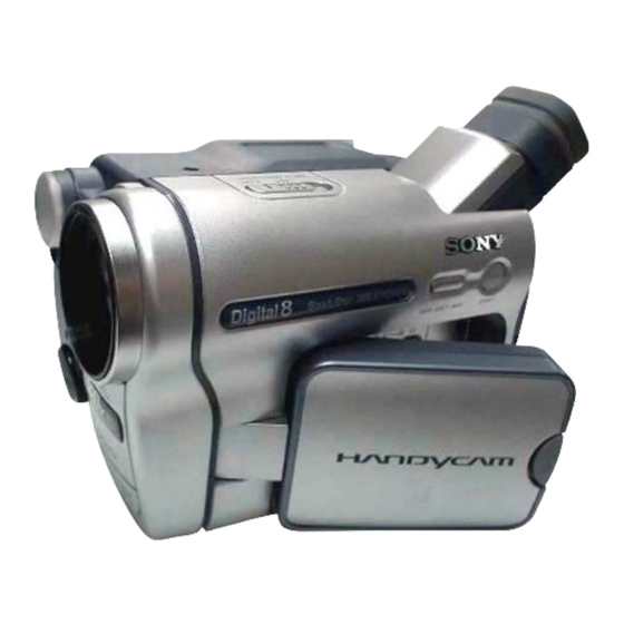
Sony Handycam DCR-TRV265E Service Manual
Rmt-830 video camera recorder
Hide thumbs
Also See for Handycam DCR-TRV265E:
- Operation manual (100 pages) ,
- Brochure & specs (28 pages)
Table of Contents
Advertisement
DCR-TRV255E/TRV260/TRV265/TRV265E
SERVICE MANUAL
Ver 1.0 2003. 11
Revision History
Revision History
How to use
How to use
Acrobat Reader
Acrobat Reader
M2200 MECHANISM
Link
Link
SPECIFICATIONS
SPECIFICATIONS
SERVICE NOTE
SERVICE NOTE
DISASSEMBLY
DISASSEMBLY
NTSC MODEL: DCR-TRV260/TRV265
PAL MODEL: DCR-TRV255E/TRV265E
• For ADJUSTMENTS (SECTION 6), refer to SERVICE MANUAL, ADJ (987629251.pdf).
• For INSTRUCTION MANUAL, refer to SERVICE MANUAL, LEVEL 1 (987629241.pdf).
• For MECHANISM ADJUSTMENTS, refer to the "8mm Video MECHANICAL ADJUSTMENT MANUAL IX
M2000 MECHANISM " (9-929-861-11).
• Reference No. search on printed wiring boards is available.
• Table for differences of function of each model.
• TO TAKE OUT A CASSETTE WHEN NOT EJECT (FORCE EJECT)
• When the machine needs to be repaired, make sure to follow the items of "LCD TYPE CHECK".
• Changing the data is needs when IC4501 is replaced, make sure to follow the items of "CHANGE OF IC4501".
• HELP: Sheet attachment positions and procedures of processing the flexible boards/harnesses are shown.
Photo: DCR-TRV265
BLOCK DIAGRAMS
BLOCK DIAGRAMS
FRAME SCHEMATIC DIAGRAMS
FRAME SCHEMATIC DIAGRAMS
SCHEMATIC DIAGRAMS
SCHEMATIC DIAGRAMS
Canadian Model
East European Model
North European Model
DCR-TRV260/TRV265/TRV265E
Australian Model
PRINTED WIRING BOARDS
PRINTED WIRING BOARDS
REPAIR PARTS LIST
REPAIR PARTS LIST
VIDEO CAMERA RECORDER
RMT-830
US Model
DCR-TRV260
AEP Model
UK Model
DCR-TRV255E/TRV265E
E Model
DCR-TRV265E
Tourist Model
DCR-TRV265/TRV265E
Advertisement
Table of Contents

Summarization of Contents
Specifications
System
Details the video recording and audio recording systems of the camera.
Input/Output Connectors
Details the S-Video, A/V, DV, and USB connectors on the unit.
LCD Screen
Information on the LCD screen size and total dot number.
General
Covers power requirements, operating/storage temperatures, and dimensions.
AC Adaptor
Specifications for the AC-L15A/L15B AC adaptor.
Rechargeable Battery Pack
Specifications for the NP-FM30 rechargeable battery pack.
Service Note
Note for Repair
Important precautions for handling flat cables and connectors during repair.
Power Supply During Repairs
Method to prevent power shut-off when using a regulated power supply.
Force Eject Cassette
Step-by-step guide to remove a cassette when the unit does not eject.
LCD Type Check
Procedure to check and discriminate the LCD type using an adjustment remote.
Self-Diagnosis Function
Explains the self-diagnosis function and how to access service mode display.
Change of IC4501
Methods to discriminate and change IC4501 versions for mechanism control.
Disassembly
Flow Chart
Illustrates the step-by-step procedure for disassembling the unit.
Mechanism Deck Service Position
Instructions on how to set the unit to access the mechanism deck.
LCD Service Position
Procedure for accessing the LCD panel and its related components.
Circuit Boards Location
Identifies the location of CD-471, VC-344, PD-204, and SI-041 boards.
Flexible Boards Location
Shows the locations of various flexible boards like FP-792, FP-796, etc.
Block Diagrams
Overall Block Diagrams
Presents the overall system block diagrams, broken down into five parts.
Power Block Diagrams
Details the power distribution and control block diagrams in two parts.
Printed Wiring Boards and Schematic Diagrams
Frame Schematic Diagram
Schematic diagram showing the frame and main board connections.
Schematic Diagrams
Collection of detailed schematic diagrams for all major boards and flexible circuits.
Printed Wiring Boards
Layout diagrams showing component placement and connections on circuit boards.
Mounted Parts Location
Visual representation of component locations on the VC-344 board.
Repair Parts List
Exploded Views
Illustrated breakdowns of the camera’s assemblies with part numbers.
Electrical Parts List
Comprehensive list of electrical components with part numbers and descriptions.


Need help?
Do you have a question about the Handycam DCR-TRV265E and is the answer not in the manual?
Questions and answers