
Related Manuals for Sony KV-HR32M31


Summarization of Contents
SECTION 1 SELF DIAGNOSIS FUNCTION
Summary of Self-Diagnosis Function
Provides an overview of the TV's self-diagnosis capabilities.
Diagnosis Items and Prediction of Malfunction Location
Lists diagnostic items, blink counts, probable causes, and detected symptoms.
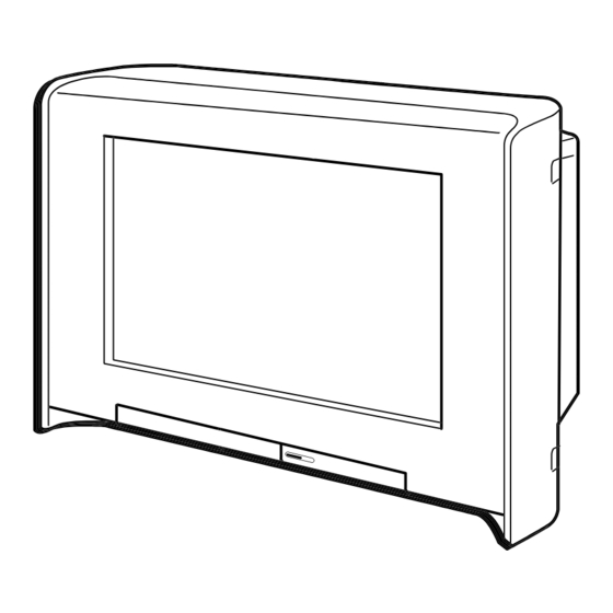
SECTION 2 DISASSEMBLY
REAR COVER ASSEMBLY
Instructions for removing the television's rear cover.
CHASSIS ASSEMBLY
Steps to remove or access the main chassis assembly.
SERVICE POSITION
Describes how to position the TV for servicing.
SPEAKER BOX ASSEMBLY
Details the removal or installation of the speaker box.
SECTION 2 DISASSEMBLY
T (HR32M31) AND UG BOARDS
Details the removal of T and UG boards, specific to HR32M31.
BM AND MG BOARDS
Instructions for disassembling BM and MG boards.
A BOARD
Procedures related to the A board.
SECTION 2 DISASSEMBLY
D BOARD
Instructions for disassembling the D board.
SF BOARD
Procedures for disassembling the SF board.
H3, H4, H5 AND HMG BOARDS
Details the disassembly of multiple boards: H3, H4, H5, and HMG.
SECTION 2 DISASSEMBLY
HARNESS ARRANGEMENT
Shows how internal harnesses are routed and connected.
SECTION 2 DISASSEMBLY
REMOVAL OF ANODE-CAP
Step-by-step guide for safely removing the anode cap.
HOW TO HANDLE AN ANODE-CAP
Provides precautions for handling the anode cap to avoid damage.
SECTION 2 DISASSEMBLY
CRT
Details the disassembly procedures for the CRT assembly.
SECTION 3 SERVICE MODE
METHOD OF SETTING THE SERVICE ADJUSTMENT MODE
Instructions on how to enter the TV's service mode.
SERVICE MODE ADJUSTMENT
Details the process of adjusting settings within the service mode.
MEMORY WRITE CONFIRMATION METHOD
Describes the procedure for saving service mode adjustments.
ADJUSTING BUTTONS AND INDICATOR
Identifies controls and indicators used for service mode adjustments.
SERVICE MODE LIST
A comprehensive list of adjustable parameters in service mode.
SECTION 4 SET-UP ADJUSTMENTS
SET-UP ADJUSTMENTS
General guidelines for performing setup adjustments when a new picture tube is installed or realignment is needed.
INITIALIZING SFC DATA
Steps to initialize SFC data, likely for picture settings adjustments.
BEAM LANDING
Adjusts the convergence of electron beams for picture alignment.
CONVERGENCE ADJUSTMENT
Details the process of adjusting picture convergence for optimal display.
G2 (SCREEN) ADJUSTMENT
Adjusts the screen brightness or G2 voltage for optimal picture.
FOCUS ADJUSTMENT 1
The first step in adjusting picture focus for sharpness.
SECTION 4 SET-UP ADJUSTMENTS
Dynamic Convergence Adjustment
Details dynamic convergence adjustments for picture alignment.
G2 (SCREEN) ADJUSTMENT
Adjusts the screen brightness or G2 voltage for optimal picture.
FOCUS ADJUSTMENT 1
The first step in adjusting picture focus for sharpness.
SECTION 4 SET-UP ADJUSTMENTS
NECK ASSY TWIST ADJUSTMENT
Adjusts the twist of the neck assembly for picture alignment.
PICTURE DISTORTION ADJUSTMENT
Corrects geometric distortions in the picture.
SFC COARSE ADJUSTMENT
Performs coarse adjustments for SFC, likely related to picture signal processing.
SECTION 4 SET-UP ADJUSTMENTS
Landing Adjustment
Procedure for adjusting picture landing or alignment.
SECTION 4 SET-UP ADJUSTMENTS
Convergence Adjustment
Details the adjustment ranges for picture convergence based on position.
SFC FINE ADJUSTMENT
Performs fine adjustments for SFC, likely related to picture signal processing.
SECTION 4 SET-UP ADJUSTMENTS
Convergence
Refers to the convergence adjustments, likely fine-tuning.
P & P SUB CONTRAST ADJUSTMENT (VIDEO) (NTSC/PAL)
Adjusts contrast for P&P sub-video signals in NTSC/PAL.
SECTION 4 SET-UP ADJUSTMENTS
P & P SUB-HUE AND SUB-COLOR ADJUSTMENT (VIDEO) (NTSC/PAL)
Adjusts hue and sub-color for P&P video signals in NTSC/PAL.
WHITE BALANCE ADJUSTMENT
Procedure to adjust the TV's white balance for accurate color reproduction.
FOCUS ADJUSTMENT 2
The second part of the focus adjustment procedure for picture clarity.
SECTION 5 SAFETY RELATED ADJUSTMENTS
SAFETY RELATED ADJUSTMENTS
Procedures related to safety adjustments and checks for the TV.
HV REGULATION CIRCUIT ADJUSTMENT
Adjusts the high voltage regulation circuit for stable operation.
HV PROTECTOR CIRCUIT CHECK
Verifies the functionality of the high voltage protector circuit.
IK PROTECTOR CIRCUIT CHECK (D BOARD)
Checks the IK protector circuit on the D board for safety.
SECTION 5 SAFETY RELATED ADJUSTMENTS
+B MAX VOLTAGE CONFIRMATION
Confirms the maximum voltage on the +B line, a critical safety check.
SECTION 6 DIAGRAMS
BLOCK DIAGRAM (1)
Illustrates the first block diagram of the TV's signal flow.
CIRCUIT BOARDS LOCATION
Shows the physical layout of circuit boards within the TV.
SCHEMATIC DIAGRAMS
Detailed schematics for various circuit boards.
PRINTED WIRING BOARDS
Illustrates the layout of the printed wiring for different circuit boards.
WAVEFORMS
Displays typical waveforms for troubleshooting and adjustment.
SEMICONDUCTORS
Lists semiconductor components used in the TV.
SECTION 6 DIAGRAMS
BLOCK DIAGRAM (2)
Second block diagram illustrating the TV's signal flow.
SECTION 6 DIAGRAMS
BLOCK DIAGRAM (2)
Second block diagram illustrating the TV's signal flow.
SECTION 6 DIAGRAMS
BLOCK DIAGRAM (2)
Second block diagram illustrating the TV's signal flow.
SECTION 6 DIAGRAMS
BLOCK DIAGRAM (3)
Third block diagram illustrating the TV's signal flow.
SECTION 6 DIAGRAMS
BLOCK DIAGRAM (4)
Fourth block diagram illustrating the TV's signal flow.
SECTION 6 DIAGRAMS
BLOCK DIAGRAM (5)
Fifth block diagram illustrating the TV's signal flow.
SECTION 6 DIAGRAMS
BLOCK DIAGRAM (6)
Sixth block diagram illustrating the TV's signal flow.
SECTION 6 DIAGRAMS
BLOCK DIAGRAM (7)
Seventh block diagram illustrating the TV's signal flow.
SECTION 6 DIAGRAMS
BLOCK DIAGRAM (8)
Eighth block diagram illustrating the TV's signal flow.
SECTION 6 DIAGRAMS
BLOCK DIAGRAM (9)
Ninth block diagram illustrating the TV's signal flow.
SECTION 6 DIAGRAMS
BLOCK DIAGRAM (10)
Tenth block diagram illustrating the TV's signal flow.
SECTION 6 DIAGRAMS
BLOCK DIAGRAM (11)
Eleventh block diagram illustrating the TV's signal flow.
SECTION 7 EXPLODED VIEWS
CHASSIS SECTION
An exploded view of the TV's chassis and main components.
SECTION 7 EXPLODED VIEWS
SUPER WOOFER BLOCK
Exploded view of the super woofer assembly.
SECTION 7 EXPLODED VIEWS
CRT SECTION
Exploded view of the Cathode Ray Tube assembly.
SECTION 7 EXPLODED VIEWS
BEZEL SECTION
Exploded view of the TV's bezel and front panel components.
Need help?
Do you have a question about the KV-HR32M31 and is the answer not in the manual?
Questions and answers