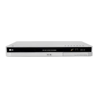

Related Manuals for LG DR175


Summarization of Contents
SECTION 1 SUMMARY
PRODUCT SAFETY SERVICING GUIDELINES FOR VIDEO PRODUCTS
Essential safety notices and precautions for servicing video products.
SERVICING PRECAUTIONS
Guidelines and precautions to follow during servicing of the DVD recorder.
SERVICE INFORMATION FOR EEPROM IC SETTING
Details on setting parameters for the EEPROM IC.
FLASH UPGRADE
Procedure for upgrading the device's flash memory.
LOADER UPGRADE
Procedure for upgrading the loader firmware.
SPECIFICATIONS
Technical specifications of the DVD recorder.
SECTION 2 CABINET & MAIN CHASSIS
EXPLODED VIEWS
Visual representation of the device's components and their assembly.
Deck Mechanism Section(RS-01A)
Exploded view of the disc loading and playback mechanism.
Packing Accessory Section
List and illustration of included accessories and packaging materials.
SECTION 3 ELECTRICAL
ELECTRICAL TROUBLESHOOTING GUIDE
Systematic guide to diagnose and resolve electrical issues.
BLOCK DIAGRAMS
System-level diagrams illustrating the interconnections of major functional blocks.
CIRCUIT DIAGRAMS
Detailed schematics showing the electronic components and their connections.
PRINTED CIRCUIT DIAGRAMS
Visual layout of components and traces on the main circuit boards.
SECTION 4 RS-01A LOADER PART
ELECTRICAL TROUBLESHOOTING GUIDE
Guide to diagnose and resolve electrical issues specific to the loader part.
THE DIFFERENCE OF DVD-R/RW, DVD+R/RW DISCS AND DVD-ROM
Comparison of different disc types and their recording formats.
HOW TO USE TEST TOOL
Instructions on using specific tools for testing and calibration.
INTERNAL STRUCTURE OF THE PICK-UP
Detailed breakdown of the optical disc reading mechanism.
DESCRIPTION OF CIRCUIT
Explanation of the functionality of specific circuits within the unit.
MAJOR IC INTERNAL BLOCK DIAGRAM
Block diagrams illustrating the internal functions of key integrated circuits.
CIRCUIT DIAGRAMS
Schematics for various sections of the loader part.
CIRCUIT VOLTAGE CHART
Reference table of voltage measurements at various IC pins.
PRINTED CIRCUIT DIAGRAMS
Layouts of the printed circuit boards for the loader part.
Need help?
Do you have a question about the DR175 and is the answer not in the manual?
Questions and answers