Table of Contents
Advertisement
SPLIT-TYPE AIR CONDITIONERS
OUTDOOR UNIT
SERVICE MANUAL
Models
MUZ-D30NA / -
MUZ-D36NA / -
MUY-D30NA / -
MUY-D36NA / -
NOTE:
RoHS compliant products have <G> mark on the spec name plate.
HFC
utilized
R410A
/ -
/ -
1
U1
U2
/ -
/ -
1
U1
U2
1
1
CONTENTS
1. TECHNICAL CHANGES ··································· 3
2. PART NAMES AND FUNCTIONS ····················· 3
3. SPECIFICATION ················································ 4
4. OUTLINES AND DIMENSIONS ························ 6
5. WIRING DIAGRAM ············································ 7
6. REFRIGERANT SYSTEM DIAGRAM ··············11
7. DATA ································································ 13
8. ACTUATOR CONTROL ··································· 20
9. SERVICE FUNCTIONS ··································· 21
10. TROUBLESHOOTING ····································· 22
11. DISASSEMBLY INSTRUCTIONS ···················· 41
PARTS CATALOG (OBB502)
• Errors in TROUBLESHOOTING have been
corrected.
Please void OBH502 REVISED EDITION-B.
No. OBH502
REVISED EDITION-C
Indoor unit service manual
MSZ-D•NA Series (OBH501)
MSY-D•NA Series (OBH501)
TM
Advertisement
Table of Contents
Troubleshooting

Related Manuals for Mitsubishi MUY-D36NA


Summarization of Contents
Technical Changes and Model Identification
New Model Introduction
Details on newly introduced models and their designations.
Wiring and Fan Motor Updates
Describes changes in wiring diagrams and fan motor specifications.
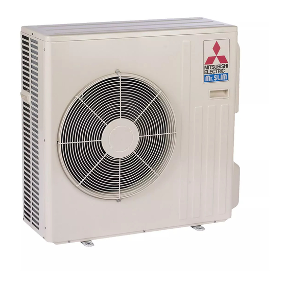
Part Names and Functions
Outdoor Unit Component Identification
Visual identification of parts like air inlet, piping, and drain.
Specifications
Capacity and Power Ratings
Cooling and heating capacities, power usage details.
Electrical and Refrigerant Specifications
Power supply, refrigerant control, piping details, dimensions, and weight.
Outlines and Dimensions
Unit Dimensions and Installation Space
Detailed measurements, overall view, and required clearance.
Wiring Diagram
Electrical Schematics and Component Symbols
Detailed wiring diagrams for outdoor units and their component symbols.
Refrigerant System Diagram
Refrigerant Flow Diagrams
Diagrams showing refrigerant flow for MUZ/MSZ and MUY models.
Data
Performance Data Tables
Cooling and heating capacity tables, operating ranges.
Performance Curves
Graphs showing capacity and input correction by frequency.
Condensing Pressure Charts
Graphs detailing condensing and suction pressure based on temperatures.
Standard Operation Data
Table of standard operational data for various models.
Actuator Control
Fan Motor and Reversing Valve Control
Control logic for outdoor fan motor and 4-way reversing valve.
Sensor to Actuator Relationship
How different sensors influence actuator operation.
Service Functions
Pre-Heat and Defrost Setting Adjustments
Procedures for activating pre-heat and changing defrost finish temperature.
Troubleshooting
Troubleshooting Cautions and Procedures
Safety guidelines, initial checks, and basic troubleshooting steps.
Failure Mode Recall Function
Procedure to recall and diagnose past intermittent operational failures.
Outdoor Unit Failure Mode Table
Links LED indications to specific failure points and recommended remedies.
Troubleshooting Flowcharts and Component Checks
Step-by-step diagnostic guides for various components and issues.
Test Point Diagrams and Voltages
Diagrams showing test points on P.C. boards and associated voltage checks.
Disassembly Instructions
Cabinet Removal
Instructions for safely removing the outdoor unit's cabinet panels.
Internal Component Removal
Procedures for removing P.C. boards, motors, coils, and other internal parts.
Sensor and Fan Motor Removal
Steps to remove thermistors, fan motor, and related components.
Major Component Removal
Procedures for removing the compressor, 4-way valve, and reactor.
Need help?
Do you have a question about the MUY-D36NA and is the answer not in the manual?
Questions and answers