Table of Contents
Advertisement
This service information is designed for experienced repair technicians only and is not designed for use by the general public.
It does not contain warnings or cautions to advise non-technical individuals of potential dangers in attempting to service a product.
Products powered by electricity should be serviced or repaired only by experienced professional technicians. Any attempt to service
or repair the products dealt with in this service information by anyone else could result in serious injury or death.
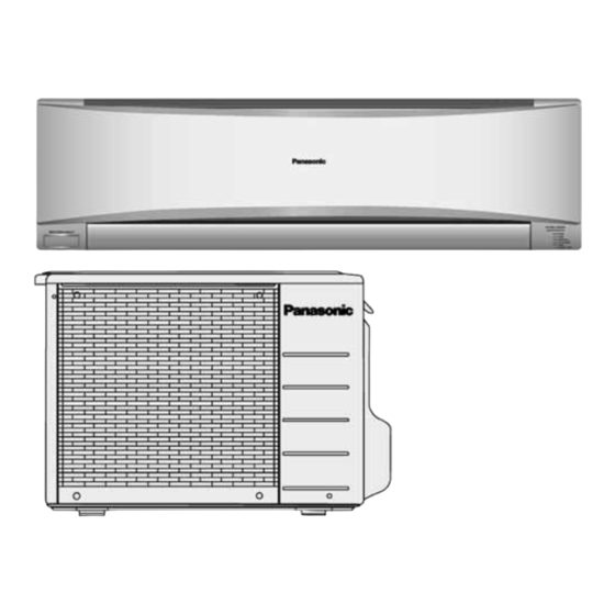
Indoor Unit
CS-C7MKP-7
CS-C9MKP-7
CS-C12MKP-7
CS-C18MKP-7
CS-C24MKP-7
WARNING
© Panasonic HA Air-Conditioning (M) Sdn. Bhd. 2011.
Unauthorized copying and distribution is a violation of law.
Order No: PHAAM1106129C3
Outdoor Unit
CU-C7MKP-7
CU-C9MKP-7
CU-C12MKP-7
CU-C18MKP-7
CU-C24MKP-7
Advertisement
Table of Contents

Related Manuals for Panasonic CS-C9MKP-7


Summarization of Contents
Service Manual
Model Identification
Lists Indoor and Outdoor unit model numbers for reference.
Safety Precautions
General Safety Guidelines
Essential safety rules for servicing and installation.
Warning Symbol Definitions
Explains the meaning of warning, caution, and prohibition symbols.
Safety Precautions
Mandatory Safety Procedures
Details specific actions to avoid during repair and installation.
Safety Precautions
Cautionary Installation Advice
Provides cautionary steps for installation to prevent minor issues.
Specifications
Model Specifications (CS-C7/C9MKP-7)
Technical data for CS-C7MKP-7 and CS-C9MKP-7 models.
Specifications
Dimensional and Operating Specifications
Details unit dimensions and operating ranges.
Specifications
Model Specifications (CS-C12MKP-7)
Technical data for CS-C12MKP-7 model.
Specifications
Dimensional and Piping Specs (CS-C7/C9/C12MKP-7)
Further dimension and piping specs for earlier models.
Specifications
Model Specifications (CS-C18/C24MKP-7)
Technical data for CS-C18MKP-7 and CS-C24MKP-7 models.
Specifications
Dimensional and Piping Specs (CS-C18/C24MKP-7)
Dimension and piping specs for CS-C18/C24MKP-7 models.
Features
Air Purifying and Piping Features
Details E-ion purification, long piping, and quality improvements.
Location of Controls and Components
Unit Component Identification
Identifies parts on indoor and outdoor units and the remote control.
Dimensions
Indoor Unit Dimensions (CS-C7/C9/C12MKP-7)
Detailed dimensions for CS-C7/C9/C12MKP-7 indoor units.
Dimensions
Indoor Unit Dimensions (CS-C18/C24MKP-7)
Detailed dimensions for CS-C18/C24MKP-7 indoor units.
Dimensions
Outdoor Unit Dimensions (CU-C7/C9/C12MKP-7)
Detailed dimensions for CU-C7/C9/C12MKP-7 outdoor units.
Dimensions
Outdoor Unit Dimensions (CU-C24MKP-7)
Detailed dimensions for CU-C24MKP-7 outdoor unit.
Refrigeration Cycle Diagram
System Flow Diagram
Illustrates the refrigerant flow between indoor and outdoor units.
Block Diagram
Power Circuit Diagram (CS-C7/C9/C12MKP-7)
Shows the main electrical components and connections for smaller models.
Block Diagram
Power Circuit Diagram (CS-C18/C24MKP-7)
Shows the main electrical components and connections for larger models.
Wiring Connection Diagram
Model Wiring Diagrams and Resistance Values
Wiring diagrams and motor/compressor winding resistance for CS-C7/C9/C12MKP-7.
Wiring Connection Diagram
Model Wiring Diagrams and Resistance Values (CS-C18MKP-7)
Wiring diagrams and resistance values for CS-C18MKP-7 units.
Wiring Connection Diagram
Model Wiring Diagrams and Resistance Values (CS-C24MKP-7)
Wiring diagrams and resistance values for CS-C24MKP-7 units.
Electronic Circuit Diagram
Circuit Diagram and Sensor Characteristics
Electronic circuit for CS-C7/C9/C12MKP-7, plus sensor resistance curves.
Electronic Circuit Diagram
Circuit Diagram (CS-C18/C24MKP-7)
Electronic circuit diagram for CS-C18/C24MKP-7 indoor units.
Electronic Circuit Diagram
Circuit Diagram (CS-C24MKP-7)
Electronic circuit diagram for CS-C24MKP-7 indoor units.
Printed Circuit Board (PCB) Layout
Indoor Unit Main PCB (CS-C7/C9/C12MKP-7)
Layout of the main printed circuit board for smaller indoor units.
Printed Circuit Board (PCB) Layout
Indoor Unit Main PCB (CS-C18/C24MKP-7)
Layout of the main PCB for larger indoor units.
Indoor Unit Indicator PCB
Layout of the indicator PCB for indoor units.
Printed Circuit Board (PCB) Layout
Receiver, High Voltage, Comparator PCBs
Layouts for receiver, HV power supply, and comparator PCBs.
Printed Circuit Board (PCB) Layout
Human Activity Sensor PCBs
Layouts for the human activity sensor PCBs.
Installation Instructions
Location Selection and Diagram
Guidance on choosing installation locations and a visual installation guide.
Installation Instructions
Indoor Unit Plate Mounting and Wall Hole
Steps for mounting the installation plate and drilling wall holes.
Installation Instructions
Indoor Unit Piping and Securement
Procedures for pulling piping and securing the indoor unit.
Installation Instructions
Indoor Unit Cable and Drain Hose Connections
Connecting cables and routing drain hoses for the indoor unit.
Installation Instructions
Wire Preparation and Piping Flaring
Guidelines for wire stripping, connecting, and piping flaring.
Installation Instructions
Outdoor Unit Installation and Piping Connection
Installing the outdoor unit and connecting refrigerant piping.
Installation Instructions
Evacuation of the Refrigerant System
Procedure to remove air and moisture from the refrigeration circuit.
Installation Instructions
Outdoor Unit Cable Connection and Pipe Insulation
Connecting outdoor unit cable and insulating refrigerant pipes.
Operation Control
Cooling Operation Details
Explanation of Cooling mode, including temperature settings and time diagrams.
Operation Control
Cooling Operation Time Diagrams (CS-C18/C24MKP-7)
Time diagrams illustrating Cooling mode operation for CS-C18/C24MKP-7.
Operation Control
Soft Dry Operation Details
Explanation of Soft Dry mode, including time diagrams for CS-C7/C9/C12MKP-7.
Operation Control
Soft Dry Operation Time Diagrams (CS-C18/C24MKP-7)
Time diagrams illustrating Soft Dry mode operation for CS-C18/C24MKP-7.
Operation Control
Automatic Operation Mode
How to use Automatic mode and adjust settings.
Indoor Fan Speed Control
Fan Speed Charts and Auto Control
Fan speed tables and automatic control logic.
Indoor Fan Speed Control
Auto Fan Speed Operation Details
Specifics of auto fan speed behavior during cooling and soft dry modes.
Operation Control
Fan Speed and Abnormal Control
Manual speed control, abnormal fan motor detection, and outdoor fan speed.
Operation Control
Vertical Airflow Direction Control
Manual adjustment of vertical airflow direction.
Operation Control
Horizontal Airflow Direction Control
Auto and manual control of horizontal airflow direction.
Operation Control
Powerful and Quiet Operation Modes
How to use Powerful and Quiet modes for quick cooling and low noise.
Operation Control
Timer, Restart, and Signal Sound Controls
Timer settings, auto-restart, and remote signal feedback sounds.
Operation Control
Patrol Operation Mode
Using Patrol mode to monitor air quality and activate e-ion.
Operation Control
Patrol Sensor and E-ion System Control
Sensor control, sensitivity adjustment, and e-ion system operation.
Operation Control
Patrol Operation Features and Indicators
Airflow control, LED displays, and timer/power failure handling in Patrol mode.
Operation Control
Patrol Operation Demo Mode
Instructions for activating and using the Patrol operation demonstration mode.
Operation Control
E-ion Operation Functionality
Details on E-ion operation start/stop conditions, fan control, and airflow.
Operation Control
E-ion Check and Abnormality Modes
Procedures for checking e-ion sensor malfunctions and abnormality modes.
Operation Control
E-ion Error Detection and Reset
Handling e-ion system errors, detection, and reset methods.
Operation Control
AUTO COMFORT and ECO NAVI Operation
Functionality of AUTO COMFORT and ECO NAVI modes, and human activity judgment.
Operation Control
Human Activity Detection and Analysis
Signal detection, information logging, area classification, and position analysis.
Operation Control
Activity Level and Louver Position Settings
Adjusting louver position and timing based on activity level.
Operation Control
ECO NAVI/AUTO COMF Demo Modes
Instructions for activating and using demo modes for ECO NAVI and AUTO COMFORT.
Operation Control
Infrared Sensor Abnormality and Check
Procedures for detecting and checking infrared sensor abnormalities.
Protection Control
Compressor Restart and Time Save Controls
Details restart control, 7-minute time save, 60-sec forced operation, and starting current control.
Protection Control
Freeze Prevention and Reverse Rotation Protection
Controls to prevent freezing and compressor damage from reverse rotation.
Protection Control
Dew Prevention Control
Mechanism to prevent dew formation on the indoor unit discharge.
Servicing Mode
Auto OFF/ON Button Functions
Using the Auto OFF/ON button for servicing modes like Test Run and Settings.
Servicing Mode
Remote Control Settings Adjustments
Adjusting transmission codes, air quality sensor, and timer intensity/display.
Troubleshooting Guide
Refrigeration Cycle Diagnosis
Diagnosing issues by measuring air temperatures, electric current, and gas pressure.
Troubleshooting Guide
Air Conditioner Conditions and Compressor Faults
Relating conditions to pressure/current, and diagnosing compressor malfunctions.
Disassembly and Assembly Instructions
Indoor Unit Front Grille and Power Controller Removal
Steps to remove the front grille and power electronic controller.
Disassembly and Assembly Instructions
Indoor Unit Controller and Discharge Grille Removal
Procedures for removing the main controller and discharge grille.
Disassembly and Assembly Instructions
Indoor Unit Control Board and Fan Motor Removal
Steps to remove the control board, cross flow fan, and motor.
Disassembly and Assembly Instructions
Indoor Unit Evaporator and Fan Removal
Procedures for removing the evaporator and cross flow fan assemblies.
Disassembly and Assembly Instructions
Indoor Unit Grille and Vane Removal (CS-C18/C24MKP-7)
Removing front grille and horizontal vane for larger indoor units.
Disassembly and Assembly Instructions
Indoor Unit Controller Removal (CS-C18/C24MKP-7)
Steps to remove the power electronic controller for larger indoor units.
Disassembly and Assembly Instructions
Indoor Unit Discharge Grille and Fan Removal (CS-C18/C24MKP-7)
Removing discharge grille, control board, and fan components for larger indoor units.
Disassembly and Assembly Instructions
Indoor Unit Evaporator and Fan Removal (CS-C18/C24MKP-7)
Procedures for removing evaporator and fan assemblies for larger indoor units.
Technical Data
Thermostat Characteristics Graphs
Graphs illustrating thermostat behavior in Cooling and Soft Dry modes.
Technical Data
Performance Characteristics (CS-C7/CU-C7MKP-7)
Performance data graphs for CS-C7/CU-C7MKP-7 models under varying conditions.
Technical Data
Piping Length Performance (CS-C7/CU-C7MKP-7)
How piping length affects performance for CS-C7/CU-C7MKP-7 units.
Technical Data
Performance Characteristics (CS-C9/CU-C9MKP-7)
Performance data graphs for CS-C9/CU-C9MKP-7 models under varying conditions.
Technical Data
Piping Length Performance (CS-C9/CU-C9MKP-7)
How piping length affects performance for CS-C9/CU-C9MKP-7 units.
Technical Data
Performance Characteristics (CS-C12/CU-C12MKP-7)
Performance data graphs for CS-C12/CU-C12MKP-7 models under varying conditions.
Technical Data
Piping Length Performance (CS-C12/CU-C12MKP-7)
How piping length affects performance for CS-C12/CU-C12MKP-7 units.
Technical Data
Performance Characteristics (CS-C18/CU-C18MKP-7)
Performance data graphs for CS-C18/CU-C18MKP-7 models under varying conditions.
Technical Data
Piping Length Performance (CS-C18/CU-C18MKP-7)
How piping length affects performance for CS-C18/CU-C18MKP-7 units.
Technical Data
Performance Characteristics (CS-C24/CU-C24MKP-7)
Performance data graphs for CS-C24/CU-C24MKP-7 models under varying conditions.
Technical Data
Piping Length Performance (CS-C24/CU-C24MKP-7)
How piping length affects performance for CS-C24/CU-C24MKP-7 units.
Exploded View and Replacement Parts List
Indoor Unit Exploded View (CS-C7/C9/C12MKP-7)
Exploded diagram of indoor unit parts for CS-C7/C9/C12MKP-7 models.
Exploded View and Replacement Parts List
Indoor Unit Parts List (CS-C7/C9/C12MKP-7)
List of replacement parts for CS-C7/C9/C12MKP-7 indoor units.
Exploded View and Replacement Parts List
Indoor Unit Parts List Continuation
Continues the parts list for CS-C7/C9/C12MKP-7 indoor units.
Exploded View and Replacement Parts List
Indoor Unit Exploded View (CS-C18/C24MKP-7)
Exploded diagram of indoor unit parts for CS-C18/C24MKP-7 models.
Exploded View and Replacement Parts List
Indoor Unit Parts List (CS-C18/C24MKP-7)
List of replacement parts for CS-C18/C24MKP-7 indoor units.
Exploded View and Replacement Parts List
Indoor Unit Parts List Continuation
Continues the parts list for CS-C18/C24MKP-7 indoor units.
Exploded View and Replacement Parts List
Outdoor Unit Exploded View (CU-C7/C9/C12MKP-7)
Exploded diagram of outdoor unit parts for CU-C7/C9/C12MKP-7 models.
Exploded View and Replacement Parts List
Outdoor Unit Parts List (CU-C7/C9/C12MKP-7)
List of replacement parts for CU-C7/C9/C12MKP-7 outdoor units.
Exploded View and Replacement Parts List
Outdoor Unit Exploded View (CU-C18MKP-7)
Exploded diagram of outdoor unit parts for CU-C18MKP-7 model.
Exploded View and Replacement Parts List
Outdoor Unit Parts List (CU-C18MKP-7)
List of replacement parts for CU-C18MKP-7 outdoor unit.
Exploded View and Replacement Parts List
Outdoor Unit Exploded View (CU-C24MKP-7)
Exploded diagram of outdoor unit parts for CU-C24MKP-7 model.
Exploded View and Replacement Parts List
Outdoor Unit Parts List (CU-C24MKP-7)
List of replacement parts for CU-C24MKP-7 outdoor unit.
Need help?
Do you have a question about the CS-C9MKP-7 and is the answer not in the manual?
Questions and answers