Table of Contents
Advertisement
Quick Links
TECHNICAL MANUAL
HYPER INVERTER PACKAGED AIR-CONDITIONERS
(Split system, Air to air heat pump type)
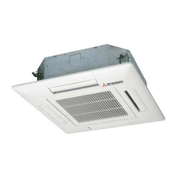
CEILING CASSETTE-4 WAY TYPE
Single type
FDT40ZJXVF
50ZJXVF
60ZJXVF
71VNXVF
100VNXVF
100VSXVF
125VNXVF
125VSXVF
140VNXVF
140VSXVF
CEILING SUSPENDED TYPE
Single type
FDEN40ZJXVF
50ZJXVF
60ZJXVF
71VNXVF
100VNXVF
100VSXVF
125VNXVF
125VSXVF
140VNXVF
140VSXVF
DUCT CONNECTED-HIGH STATIC PRESSURE TYPE
Single type
FDU71VNXVD
100VNXVD
100VSXVD
125VNXVD
125VSXVD
140VNXVD
140VSXVD
WALL MOUNTED TYPE
Twin type
SRK100VNXPZJX
100VSXPZJX
125VNXPZJX
125VSXPZJX
Twin type
FDT71VNXPVF
100VNXPVF
100VSXPVF
125VNXPVF
125VSXPVF
140VNXPVF
140VSXPVF
Triple type
FDT140VNXTVF
140VSXTVF
Twin type
FDEN71VNXPVF
100VNXPVF
100VSXPVF
125VNXPVF
125VSXPVF
140VNXPVF
140VSXPVF
Triple type
FDEN140VNXTVF
140VSXTVF
Triple type
SRK140VNXTZJX
140VSXTZJX
Manual No. '12
CEILING CASSETTE-4 WAY COMPACT TYPE
Single type
Triple type
FDTC40ZJXVF
50ZJXVF
60ZJXVF
Twin type
FDTC71VNXPVF
100VNXPVF
100VSXPVF
125VNXPVF
125VSXPVF
DUCT CONNECTED-LOW/MIDDLE STATIC PRESSURE TYPE
Single type
Twin type
FDUM50ZJXVF
60ZJXVF
71VNXVF
100VNXVF
100VSXVF
125VNXVF
125VSXVF
Triple type
140VNXVF
140VSXVF
FLOOR STANDING TYPE
Single type
Twin type
FDF71VNXVD
FDF140VNXPVD
100VNXVD
100VSXVD
125VNXVD
125VSXVD
140VNXVD
140VSXVD
(OUTDOOR UNIT)
(INDOOR UNIT)
FDC71VNX
100VNX
100VSX
125VNX
125VSX
140VNX
140VSX
Pac-T-173
•
FDTC140VNXTVF
140VSXTVF
FDUM100VNXPVF
100VSXPVF
125VNXPVF
125VSXPVF
140VNXPVF
140VSXPVF
FDUM140VNXTVF
140VSXTVF
140VSXPVD
FDT40VF
FDEN40VF
50VF
50VF
60VF
60VF
71VF
71VF
100VF
100VF
125VF
125VF
Advertisement
Table of Contents
Troubleshooting

Related Manuals for Mitsubishi Heavy Industries FDC Series


Summarization of Contents
1. HYPER INVERTER PACKAGED AIR-CONDITIONERS
1.1 SPECIFICATIONS
Details of the product's technical specifications, including capacities and dimensions.
1.2 EXTERIOR DIMENSIONS
Provides physical measurements and mounting details for indoor and outdoor units.
1.3 ELECTRICAL WIRING
Details the wiring diagrams and connections for various unit series.
1.4 NOISE LEVEL
Presents sound pressure level data for different operating modes and fan speeds.
1.5 CHARACTERISTICS OF FAN
Shows fan performance curves relating airflow to external static pressure.
1.6 TEMPERATURE AND VELOCITY DISTRIBUTION
Illustrates temperature and airflow patterns for various indoor unit types.
1.7 PIPING SYSTEM
Illustrates the refrigerant piping layout for different system configurations.
1.8 RANGE OF USAGE & LIMITATIONS
Outlines operating temperature limits and installation restrictions for safe use.
1.9 SELECTION CHART
Provides guidance and tables for selecting appropriate units and calculating capacities.
1.10 APPLICATION DATA
Covers installation details for indoor and outdoor units, including pipe sets and electrical wiring.
1.11 OUTLINE OF OPERATION CONTROL BY MICROCOMPUTER
Explains various control functions and modes managed by the microcomputer.
1.12 MAINTENANCE DATA
Details troubleshooting procedures and checks for common issues and PCB replacement.
2. V MULTI SYSTEM
2.1 GENERAL INFORMATION
Explains how to read model names and provides tables for model and system combinations.
2.2 SPECIFICATIONS
Lists detailed specifications for indoor units (cassette, suspended) and outdoor units.
2.3 EXTERIOR DIMENSIONS
Provides dimensional drawings for various indoor and outdoor unit models.
2.4 ELECTRICAL WIRING
Details wiring diagrams for indoor and outdoor units, including remote controller connections.
2.5 NOISE LEVEL
Presents sound pressure level data in octave bands for indoor and outdoor units.
2.6 TEMPERATURE AND VELOCITY DISTRIBUTION
Illustrates temperature and velocity distribution charts for indoor units.
2.7 PIPING SYSTEM
Shows refrigerant piping diagrams for single, twin, and triple indoor unit configurations.
2.8 RANGE OF USAGE & LIMITATIONS
Specifies operating temperature ranges and general installation limitations.
2.9 SELECTION CHART
Provides guidance and tables for selecting appropriate units and calculating capacities.
2.10 APPLICATION DATA
Includes installation details for indoor units, electrical wiring, remote controllers, and outdoor units.
2.11 OUTLINE OF OPERATION CONTROL BY MICROCOMPUTER
Explains various control functions and modes managed by the microcomputer.
2.12 MAINTENANCE DATA
Covers troubleshooting flow, diagnosing microcomputer circuits, and maintenance data.
3. OPTION PARTS
3.1 WIRELESS KIT
Details the installation and settings for wireless remote controllers and receivers.
3.2 SIMPLE WIRED REMOTE CONTROLLER (RCH-E3)
Describes the functions and installation of the wired remote controller.
3.3 BASE HEATER KIT (CW-H-E)
Explains the components and installation procedure for the base heater kit.
3.4 INTERFACE KIT (SC-BIKN-E)
Covers the installation and wiring of the interface kit for connecting controllers.
3.5 SUPER LINK E BOARD (SC-ADNA-E)
Details the application and function of the Super Link E Board.
Need help?
Do you have a question about the FDC Series and is the answer not in the manual?
Questions and answers