Table of Contents
Advertisement
Quick Links
Instruction manual
Instruction manual
Operating & Maintenance
Operating & Maintenance
4812159801_A.pdf
4812159801_A.pdf
Vibratory roller
Vibratory roller
CC234HF/334HF
CC234HF/334HF
CC2300/3300
CC2300/3300
Cummins QSB 3.3 (IIIA/T3)
Cummins QSB 3.3 (IIIA/T3)
Deutz TCD 3.6 L04 (IIIB/T4i)
Deutz TCD 3.6 L04 (IIIB/T4i)
Serial number
Serial number
10000313x0A009396 -
10000313x0A009396 -
10000317x0A009737 -
10000317x0A009737 -
10000338x0A011354 -
10000338x0A011354 -
10000342x0A011649 -
10000342x0A011649 -
Translation of original instruction
Translation of original instruction
Reservation for changes
Reservation for changes
Printed in Sweden
Printed in Sweden
Engine
Engine
Advertisement
Table of Contents

Related Manuals for Atlas Copco CC3300


Summary of Contents for Atlas Copco CC3300
- Page 1 Instruction manual Instruction manual Operating & Maintenance Operating & Maintenance 4812159801_A.pdf 4812159801_A.pdf Vibratory roller Vibratory roller CC234HF/334HF CC234HF/334HF CC2300/3300 CC2300/3300 Engine Engine Cummins QSB 3.3 (IIIA/T3) Cummins QSB 3.3 (IIIA/T3) Deutz TCD 3.6 L04 (IIIB/T4i) Deutz TCD 3.6 L04 (IIIB/T4i)
-
Page 3: Table Of Contents
Table of Contents Introduction ..........................1 Warning symbols..................1 The machine ....................1 Intended use ....................1 Safety information ..................1 General ....................... 2 CE marking and Declaration of conformity..........3 Safety - General instructions....................5 Safety - when operating ......................7 Slopes ...................... - Page 4 Dimensions, top view ................17 Weights and volumes................18 Working capacity..................18 General ..................... 19 Hydraulic system..................20 Automatic Climate Control (ACC) (Optional)..........20 Tightening torque ..................21 Machine description ....................... 23 Diesel engine .................... 23 Electrical system ..................23 Propulsion system..................
- Page 5 Machine alarm................... 40 "MAIN MENU" ................... 41 "USER SETTINGS" ..............42 "MACHINE SETTINGS".............. 43 "SERVICE MENU" ..............43 "ABOUT"..................45 Operator help when starting..............45 Operator help Workmode................45 Instruments and controls, cab ..............46 Function description of instruments and controls in the cab ..... 47 Using the cab controls................
- Page 6 Interlock..................... 58 Operator position..................59 View ......................59 Starting ........................60 Starting the engine ..................60 Display when activating choice via the button set........61 Alarm descriptions..................62 Driving ........................63 Operating the roller ................... 63 Machine with gear change in separate spring-return switch (gear position switch)..............
- Page 7 Fuel tank ....................71 Hydraulic reservoir ..................71 Hoods, tarpaulin ..................72 Steering cylinder, hinges, etc..............72 Miscellaneous ........................73 Lifting ........................73 Locking the articulation ................73 Lifting the roller..................74 Lifting the roller with jack:................74 Unlocking the articulation ................75 Towing/Recovering....................
- Page 8 Every 500/1500 hours of operation ............90 Every 1000 hours of operation ..............91 Every 2000 hours of operation ..............92 Maintenance, 10h ........................93 Diesel engine - Check oil level ..............93 Coolant level - Check ................94 Fuel tank - Refueling ................. 94 Water tank, Std - Filling................
- Page 9 Air conditioning (Optional) Drying filter - Inspection ................106 Edge cutter (Optional) - Lubrication .................... 106 Maintenance - 500 / 1500h ....................107 Diesel engine Oil change ....................107 Engine Replacing oil filter..................108 The engine fuel filter - replacement/cleaning .......... 108 Hydraulic fluid cooler Checking - Cleaning................
- Page 10 Engine Replacing oil filter..................118 The engine fuel filter - replacement/cleaning .......... 118 Hydraulic fluid cooler Checking - Cleaning................119 Air cleaner Checking - Change the main air filter............119 Backup filter - Change................120 Air cleaner - Cleaning....................120 Battery - Check condition ..................
- Page 11 The engine fuel filter - replacement/cleaning .......... 130 Hydraulic fluid cooler Checking - Cleaning................131 Air cleaner Checking - Change the main air filter............131 Backup filter - Change................132 Air cleaner - Cleaning....................132 Battery - Check condition ..................133 Hydraulic filter Change....................
- Page 12 Steering hitch - Tightening ..............141 4812159801_A.pdf 2014-03-31...
-
Page 13: Introduction
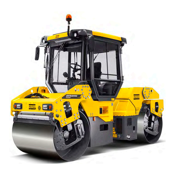
Propulsion and braking are applied to all drum halves. CC234HF/334HF, CC2300/3300 is also available as Combi with four rubber wheels at rear replacing the split steel drum. A variety of different engine power settings, operator platforms, control possibilities and options makes the machine available in a lot of different configurations. -
Page 14: General
Introduction We recommend that the operator reads the We recommend that the operator reads the safety instructions in this manual carefully. safety instructions in this manual carefully. Always follow the safety instructions. Ensure Always follow the safety instructions. Ensure that this manual is always easily accessible. that this manual is always easily accessible. -
Page 15: Ce Marking And Declaration Of Conformity
Introduction This manual contains instructions for periodic maintenance normally carried out by the operator. Additional instructions for the engine can be Additional instructions for the engine can be found in the manufactuer's engine manual. found in the manufactuer's engine manual. CE marking and Declaration of conformity (Applies to machines marketed in EU/EEC) This machine is CE marked. - Page 16 Introduction 4812159801_A.pdf 2014-03-31...
-
Page 17: Safety - General Instructions
Safety - General instructions Safety - General instructions (Also read the safety manual) The operator must be familiar with the contents of the OPERATION section The operator must be familiar with the contents of the OPERATION section before starting the roller. before starting the roller. - Page 18 Safety - General instructions 16. Hearing protection is recommended if the noise level exceeds 85 dB(A). The 16. Hearing protection is recommended if the noise level exceeds 85 dB(A). The noise level can vary depending on the equipment on the machine and the noise level can vary depending on the equipment on the machine and the surface the machine is being used on.
-
Page 19: Safety - When Operating
Safety - when operating Safety - when operating Prevent persons from entering or remaining in Prevent persons from entering or remaining in the danger area, i.e. a distance of at least 7 m the danger area, i.e. a distance of at least 7 m (23 ft) in all directions from operating machines. -
Page 20: Driving Near Edges
Safety - when operating Driving near edges When driving near an edge, minimum 2/3 of the drum width must be on solid ground. When using pivotal steering, only one drum When using pivotal steering, only one drum should be allowed to move into the position should be allowed to move into the position shown in the picture. -
Page 21: Safety (Optional)
Safety (Optional) Safety (Optional) Air conditioning The system contains pressurized refrigerant. It is The system contains pressurized refrigerant. It is forbidden to release refrigerants into the forbidden to release refrigerants into the atmosphere. atmosphere. Work on the refrigerant circuit is only to be carried Work on the refrigerant circuit is only to be carried out by authorized companies. -
Page 22: Working Lights - Xenon
Safety (Optional) Working lights - Xenon Warning, high voltage! Warning, high voltage! The working lights of the Xenon type have a secondary high-voltage source. Work on the lighting should only be conducted by an authorized electrician and with the primary voltage disconnected. -
Page 23: Special Instructions
Special instructions Special instructions Standard lubricants and other recommended oils and fluids Before leaving the factory, the systems and components are filled with the oils and fluids specified in the lubricant specification. These are suitable for ambient temperatures in the range -15°C to +40°C (5°F - 105°F). -
Page 24: High Pressure Cleaning
Special instructions High pressure cleaning Do not spray directly onto electrical components. Do not use high pressure cleaning for Do not use high pressure cleaning for dashboard/display. dashboard/display. The Electrical Drive Control and the computer The Electrical Drive Control and the computer box may not be washed with high pressure box may not be washed with high pressure cleaning and not at all with water. -
Page 25: Jump Starting (24V)
Special instructions When fitting batteries, always connect the When fitting batteries, always connect the positive cable first. positive cable first. Dispose of old batteries in an environmentally Dispose of old batteries in an environmentally friendly way. Batteries contain toxic lead. friendly way. - Page 26 Special instructions 4812159801_A.pdf 2014-03-31...
-
Page 27: Technical Specifications
Technical specifications Technical specifications Vibrations - Operator station (ISO 2631) The vibration levels are measured in accordance with the operational cycle described in The vibration levels are measured in accordance with the operational cycle described in EU directive 2000/14/EC on machines equipped for the EU market, with vibration switched EU directive 2000/14/EC on machines equipped for the EU market, with vibration switched on, on soft polymer material and with the operator’s seat in the transport position. -
Page 28: Dimensions, Side View
Technical specifications Dimensions, side view Dimensions Dimensions Wheel base Wheel base 3340 3340 Diameter, drum Diameter, drum 1150 1150 Height, with ROPS/cab Height, with ROPS/cab 2990 2990 Height, without ROPS/cab Height, without ROPS/cab 2275 2275 Ground clearance Ground clearance Length, standard variant Length, standard variant 4490 4490... -
Page 29: Dimensions, Top View
Technical specifications Dimensions, top view Dimensions Dimensions Machine width, standard Machine width, standard CC234HF, CC2300 CC234HF, CC2300 1620 1620 CC334HF, CC3300 CC334HF, CC3300 1870 1870 Machine width, asymmetrical Machine width, asymmetrical 2145 2145 84.5 84.5 Turning radius, outer Turning radius, outer... -
Page 30: Weights And Volumes
Weights Weights Service weight Service weight without ROPS without ROPS ROPS ROPS (EN500) (EN500) CC234HF, CC2300 STD CC234HF, CC2300 STD (kg) 7 800 (kg) 7 800 8 000 8 000 8 200 8 200 (lbs) 17 200 (lbs) 17 200... -
Page 31: General
(CE-2006) (CE-2006) (CE-2006) (CE-2006) CC234HF, CC2300 CC234HF, CC2300 51 (kN) 51 (kN) 16 200 16 200 16 200 16 200 13 500 13 500 11 475 (lb) 11 475 (lb) CC334HF, CC3300... -
Page 32: Hydraulic System
Technical specifications Bulbs (if mounted) Bulbs (if mounted) Watt Watt Socket Socket Drive lights, front Drive lights, front 75/70 75/70 P43t (H4) P43t (H4) Direction lights, front Direction lights, front BA9s BA9s Side lights Side lights SV8,5 SV8,5 Brake-Position lights Brake-Position lights 21/5 21/5... -
Page 33: Tightening Torque
Technical specifications Tightening torque Tightening torque in Nm for oiled or dry bolts tightened with a torque wrench. Metric coarse screw thread, bright galvanized (fzb): STRENGTH CLASS: 8.8, Oiled 8.8, Oiled 8.8, Dry 8.8, Dry 10.9, Oiled 10.9, Oiled 10.9, Dry 10.9, Dry 12.9, Oiled 12.9, Oiled... - Page 34 Technical specifications 4812159801_A.pdf 2014-03-31...
-
Page 35: Machine Description
Machine description Machine description Diesel engine The machine is equipped with a completely electronically controlled water-cooled four-cylinder, turbocharged (WGT) diesel engine with direct injection (HPCR) and intercooler. WGT - Waste Gate Turbo HPCR - High Pressure Common Rail fuel injection (IIIB/T4i) The engine is also equipped with cooled exhaust gas recirculation (ceGR) and a diesel oxidation catalysator... -
Page 36: Brake System
Machine description Brake system The brake system comprises a service brake, secondary brake and parking brake. The service brake system produces retardation of the propulsion system, i.e. hydrostatic braking. Secondary/Parking brake The secondary and parking brake system comprises sprung disc brakes to each drum, drum half respectively wheel pair.The disc brakes are disengaged by hydraulic pressure. -
Page 37: Identification
Machine description The cab is approved as a protective cab in accordance with the ROPS standard. If any part of the cab's or the ROPS structure's protective construction displays plastic deformation or cracks, the cab or the ROPS structure must be replaced immediately. -
Page 38: Product Identification Number On The Frame
Machine description Product identification number on the frame The machine PIN (Product Identification Number) (1) is punched on the right edge of the front frame. Fig. PIN Front frame Machine plate The machine type plate (1) is attached to the front left side of the frame, beside the steering joint. -
Page 39: Engine Plates
Machine description Engine plates The engine type plates (1) are affixed to the top and on the right side of the engine. The plates specify the type of engine, serial number and the engine specification. Please specify the engine serial number when ordering spares. -
Page 40: Decals
Machine description Decals Location - decals Fig. Location, decals and signs Warning, Crush zone Warning, Crush zone 4700903422 4700903422 12. Master switch 12. Master switch 4700904835 4700904835 Warning, Rotating engine Warning, Rotating engine 4700903423 4700903423 13. Coolant 13. Coolant 4700388449 4700388449 components components... -
Page 41: Safety Decals
Machine description Safety decals Always make sure that all safety decals are completely legible, and remove dirt or order new decals if they have become illegible. Use the part number specified on each decal. 4700903422 Warning - Crush zone, articulation/drum. Maintain a safe distance from the crush zone. - Page 42 Machine description 4700908229 Warning - Risk of crushing The articulation must be locked when lifting. Read the instruction manual. 4700904165 Warning - Toxic gas (option, ACC) Read the instruction manual. 4700791642 Warning - Starting gas Starting gas is not to be used. 4812159801_A.pdf 2014-03-31...
-
Page 43: Info Decals
Machine description Info decals Manual compartment Manual compartment Battery voltage Battery voltage Master switch Master switch Coolant Coolant Water Water Hydraulic fluid level Hydraulic fluid level Hydraulic fluid Hydraulic fluid Biological hydraulic fluid Biological hydraulic fluid Diesel fuel Diesel fuel Bio-hydraulic fluid PANOLIN Bio-hydraulic fluid PANOLIN Fuel with low sulphur content (IIIB/T4i) -
Page 44: Instruments/Controls
Machine description Instruments/Controls Control panel and controls 28/30/35 29/31 Fig. Control panel Ignition switch Ignition switch Vibration rear drum Vibration rear drum Parking brake Parking brake Forward & Reverse lever Forward & Reverse lever Work mode (Off-set and Work mode (Off-set and Hazard lights Hazard lights vibration permitted plus soft... -
Page 45: Function Descriptions
Machine description Functions Functions Direction indicators Direction indicators Driving lights Driving lights Full/Dipped beam Full/Dipped beam Parking lights Parking lights Horn Horn Figure. Steering column switch (optional) Function descriptions Designation Designation Symbol Symbol Function Function Ignition key Ignition key The electric circuit is broken. The electric circuit is broken. - Page 46 Machine description Designation Designation Symbol Symbol Function Function Main beam indicator Main beam indicator Shows main beam activated (Activated via the Shows main beam activated (Activated via the steering column switch). steering column switch). Amplitude selector, high Amplitude selector, high Activation produces high amplitude.
- Page 47 Machine description Designation Designation Symbol Symbol Function Function Speed limiter Speed limiter Limitation of the machine's max. speed (max.speed is Limitation of the machine's max. speed (max.speed is obtained with full deflection of the F/R lever). Set the obtained with full deflection of the F/R lever). Set the knob to the required position and read the speed on knob to the required position and read the speed on the display (30).
-
Page 48: Display Explanations
Machine description Designation Designation Symbol Symbol Function Function Position 2: Normal position Position 2: Normal position Position 3: Used for maximum transport speed or for Position 3: Used for maximum transport speed or for high speed during smooth rolling without vibration high speed during smooth rolling without vibration Edge press/cutter, UP/DOWN Edge press/cutter, UP/DOWN... - Page 49 Machine description A status screen provides information on the fuel level, water level in the sprinkler tank, machine hours and voltage level. Fuel and water levels are specified in per cent (%). This screen is active until the Diesel engine is started or an active screen choice is made via the function buttons below the display.
- Page 50 Machine description Scroll/Selection buttons to choose Scroll/Selection buttons to choose between available functions. between available functions. Alarm log button to display engine and Alarm log button to display engine and machine alarms. machine alarms. Settings/Button select menu, which opens Settings/Button select menu, which opens the main menu.
- Page 51 Machine description When an engine alarm is activated, the alarm is shown on the display. The engine alarm is sent out from the engine ECM, which handles the monitoring of the engine functions. The message, which consists of an SPN and FMI code, can be interpreted via the engine supplier error code list.
-
Page 52: Machine Alarm
Machine description Machine alarm Symbol Symbol Designation Designation Function Function Warning symbol, hydraulic fluid filter Warning symbol, hydraulic fluid filter If the symbol is shown when the diesel engine is running at If the symbol is shown when the diesel engine is running at full speed, the hydraulic fluid filter must be changed. -
Page 53: Main Menu
Machine description Alarms received are saved/logged and can be seen by selecting Display alarms. Selection of Display alarms. "ENGINE ALARM" Saved/Logged engine alarms. "MACHINE ALARM" Saved/Logged machine alarms. These alarms come from the other systems on the machine. "MAIN MENU" In the main menu it is also possible to change some user and machine settings, access the service menu for calibration purposes (special service personnel... -
Page 54: User Settings
Machine description "USER SETTINGS" Users can change the light settings, choose between the Metric or Imperial system, and set warning sounds On/Off. Adjustment of the light and contrast settings on the display, including brightness of the panel light. 4812159801_A.pdf 2014-03-31... -
Page 55: Machine Settings
Machine description "MACHINE SETTINGS" The selection "Sprinkler Pump: 1 & 2" is in machine settings. If the machine is fitted with double sprinkler pumps (Option) this is the menu in which the selection is made for which of the sprinkler pumps are to be activated to water the drum(s). - Page 56 Machine description "ADJUSTMENTS" "TESTMODES" - Installation personnel only, requires pin code. "CALIBRATION" - service personnel only, requires password. "EDC Calibration" used to calibrate the joystick and speed potentiometer. "TX Program" only used to change software in the display and requires special equipment and know-how. "EDC CALIBRATION"...
-
Page 57: About
Machine description "ABOUT" It is also possible to see the version of the installed software. Operator help when starting When trying to start the machine without having set one, two or three of the conditions required to start machine, the missing conditions are shown in the display. -
Page 58: Instruments And Controls, Cab
Machine description Instruments and controls, cab Radio/CD Fig. Cab roof, front Fig. Right rear cab post 4812159801_A.pdf 2014-03-31... -
Page 59: Function Description Of Instruments And Controls In The Cab
Machine description Function description of instruments and controls in the cab Designation Designation Symbol Symbol Function Function Heater control Heater control Turn to the right to increase heating. Turn to the right to increase heating. Turn to the left to reduce heating. Turn to the left to reduce heating. -
Page 60: Using The Cab Controls
Machine description Using the cab controls. Defroster To quickly remove ice or mist, make sure that only the front and rear air nozzles are open. Turn the heater and fan dial (1 and 2) to max. Adjust the nozzle so that it blows on the window to be de-iced, or to remove mist. -
Page 61: Electrical System (Version 1)
Machine description Electrical system (version 1) The machine's main switchbox (1) is located on the rear of the operator platform. There is a plastic cover over the distribution box and fuses. On the plastic cover there is a 24V socket. Fig. -
Page 62: Electrical System (Version 2)
Machine description Electrical system (version 2) The machine's main switchbox (1) is located on the rear of the operator platform. There is a plastic cover over the distribution box and fuses. On the plastic cover there is a 24V socket and a 12V socket (optional). -
Page 63: Power In Engine Compartment/Battery Compartment
Machine description Power in engine compartment/battery compartment The fuses in the engine compartment are located alongside the master switch. The roller is equipped with 24 V electrical system and an AC alternator. Connect the correct polarities (ground) to the Connect the correct polarities (ground) to the battery. -
Page 64: Fuse Box At Master Switch (Deutz)
Machine description Main fuse panel (Deutz) The main fuse panel is located behind the left engine compartment door. Fig. Main fuse panel 1. Master switch 2. Preheating relay (100A) 3. Starter relay 4. Power socket 24V 5. Fuse box (F4) Fuse box at master switch (Deutz) The figure shows the position of the fuses. -
Page 65: Fuses In Cab
Machine description Fuses in cab The electrical system in the cab has a separate fuse box located on the front right side of the cab roof. The figure shows fuse amperage and function. Fig. Cab roof fuse box (F7) All fuses are flat pin fuses. 1. - Page 66 Machine description 4812159801_A.pdf 2014-03-31...
-
Page 67: Operation
Operation Operation Before starting Master switch - Switching on Remember to carry out daily maintenance. Refer to the maintenance instructions. The master switch is located in the engine compartment. Turn the key (1) to the on position. The entire roller is now supplied with power. If the main battery/master switch is covered, the If the main battery/master switch is covered, the engine hood must be unlocked during operation,... -
Page 68: Operator's Seat - Adjustment
Operation Operator's seat - Adjustment Adjust the operator’s seat so that the position is comfortable and so that the controls are within easy reach. The seat can be adjusted as follows. - Length adjustment (1) - Weight adjustment (2) Fig. Operator's seat - Back support angle (3) 1. -
Page 69: Parking Brake
Operation Parking brake Ensure that the parking brake (1) is definitely Ensure that the parking brake (1) is definitely switched on. switched on. Brake is always activated in Neutral. (automatic 2 sec.) The parking brake must be activated to start the Fig. -
Page 70: Interlock
Operation Interlock The roller is equipped with Interlock. The diesel engine with switch off after 7 seconds if the operator gets off the seat when going forwards/backwards. If the control is in neutral when the operator stands up a buzzer will go on until the parking brake is activated. If the parking brake is activated, the diesel engine will not stop if the forward/reverse lever is moved out of neutral. -
Page 71: Operator Position
Operation Operator position If a ROPS (Roll Over Protective Structure) or a cab is fitted to the roller, always wear the seat belt (1) provided and wear a protective helmet. Replace the seat belt (1) if it shows signs of Replace the seat belt (1) if it shows signs of wear or has been subjected to high levels of wear or has been subjected to high levels of... -
Page 72: Starting
Operation Starting Starting the engine Make sure that the emergency stop is OFF and the parking brake ON. Set the forward/reverse lever (1) in neutral position, and set the speed selector (2) in the idling position (LO). The diesel engine cannot be started in any other position of the controls. -
Page 73: Display When Activating Choice Via The Button Set
Operation When starting and driving a machine that is cold, When starting and driving a machine that is cold, remember that the hydraulic fluid is also cold and remember that the hydraulic fluid is also cold and that braking distances can be longer than normal that braking distances can be longer than normal until the machine reaches the working temperature. -
Page 74: Alarm Descriptions
Operation Alarm descriptions Symbol Symbol Designation Designation Function Function Warning lamp, hydraulic filter Warning lamp, hydraulic filter If the lamp comes on while the engine is running at full If the lamp comes on while the engine is running at full speed, the hydraulic filter must be changed. -
Page 75: Driving
Operation Driving Operating the roller Under no circumstances is the machine to be Under no circumstances is the machine to be operated from the ground. The operator must be operated from the ground. The operator must be seated inside the machine during all operation. seated inside the machine during all operation. - Page 76 Operation The machine's gear position is shown in the center of the speedometer; select the gear/speed for the task. The machine does not need to be stopped to change gear position. Fig. The display shows the selection in the middle (position 1, 2 or 3) Max.
-
Page 77: Interlock/Emergency Stop/Parking Brake - Check
Operation Interlock/Emergency stop/Parking brake - Check The interlock, emergency stop and parking brake must The interlock, emergency stop and parking brake must be checked daily before operating. A function check of be checked daily before operating. A function check of the interlock and emergency stop requires a restart. -
Page 78: Pivotal Steering (Optional)
Operation Pivotal steering (Optional) The machine must be in the operating position to activate the pivotal steering. Use the two front buttons (1) on the forward/reverse lever to operate the pivotal steering. To reset the rear drum to neutral, adjust the buttons (1) until the display (2) shows that the machine has aligned the drums. -
Page 79: Vibration
Operation The operator can choose between two tools, the edge cutter or edge compactor. The edge cutter (1) in the figure is shown in the operating position. The edge compactor (1) can easily be replaced with the edge cutter by releasing the bolted joint (3). Fig. -
Page 80: Manual Vibration - Switching On
Operation Manual vibration - Switching on Never activate vibration when the roller is Never activate vibration when the roller is stationary. This can damage both the surface and stationary. This can damage both the surface and the machine. the machine. Engage and disengage vibration using the switch (1) on the front of the forward/reverse lever. -
Page 81: Emergency Braking
Operation If the forward/reverse lever is moved quickly (forwards or backwards) toward/past neutral, the system switches to a rapid braking Mode and the machine stops. Activate normal driving Mode again by moving the forward/reverse lever back to neutral. Emergency braking Braking is normally activated using the forward/reverse lever. -
Page 82: Parking
Operation Parking Chocking the drums Never disembark from the machine when the Never disembark from the machine when the diesel engine is running, unless the parking brake diesel engine is running, unless the parking brake is activated. is activated. Make sure that the roller is parked in a safe place Make sure that the roller is parked in a safe place with respect to other road users. -
Page 83: Long-Term Parking
Long-term parking Long-term parking The following instructions should be followed The following instructions should be followed when long term parking (more than one month). when long term parking (more than one month). These measures apply when parking for a period of up to 6 months. -
Page 84: Hoods, Tarpaulin
Long-term parking Hoods, tarpaulin * Lower the instrument cover over the instrument panel. * Cover the entire roller with a tarpaulin. A gap must be left between the tarpaulin and the ground. * If possible, store the roller indoors and ideally in a building where the temperature is constant. -
Page 85: Miscellaneous
Miscellaneous Miscellaneous Lifting Locking the articulation Articulation must be locked to prevent inadvertent Articulation must be locked to prevent inadvertent turning before lifting the roller. turning before lifting the roller. Turn the steering wheel to the straight ahead position. Push in the emergency/parking brake knob. Pull out the lowermost locking pin (1), which has a a wire attached. -
Page 86: Lifting The Roller
Miscellaneous Weight: refer to the hoisting plate on the Lifting the roller roller The machine’s gross weight is specified on the The machine’s gross weight is specified on the hoisting plate (1). Refer also to the Technical hoisting plate (1). Refer also to the Technical specifications. -
Page 87: Unlocking The Articulation
Miscellaneous Unlocking the articulation Remember to unlock the articulation before Remember to unlock the articulation before operating. operating. Pull out the lowermost locking pin (1), which has a a wire attached. Pull up the locking dowel (2) which also has a wire attached. Fold the locking arm (3) back and secure it in the locking lug (4) with the locking dowel (2). -
Page 88: Short Distance Towing With The Engine Running
Miscellaneous Short distance towing with the engine running Activate the parking brake, and temporarily stop Activate the parking brake, and temporarily stop the diesel engine. Chock the drums to prevent the the diesel engine. Chock the drums to prevent the roller from moving roller from moving Open the left door to the engine compartment to... -
Page 89: Towing The Roller
Miscellaneous Towing the roller When towing/recovering, the roller must be braked When towing/recovering, the roller must be braked by the towing vehicle. A towing bar must be used by the towing vehicle. A towing bar must be used as the roller has no brakes. as the roller has no brakes. -
Page 90: Transport
Miscellaneous Transport Tie-down and secure the machine according to the Cargo Securing Certificate for the specific machine if this is avaliable and applicable. If not, tie down and secure the machine according to the cargo securing rules that are valid for the country where the transport takes place. -
Page 91: Loading Cc224-624Hf, Cc2200-6200
Miscellaneous Loading CC224-624HF, CC2200-6200 Securing vibratory roller CC224-624HF, CC2200-6200 from Dynapac for transport. (The instructions also apply to Combi machines) Roller loaded in forward direction Direct of travel The lashings can be moved to a rear point on the roller if there is no edge line on the trailer. The lashings can be moved to a rear point on the roller if there is no edge line on the trailer. - Page 92 Operating instructions - Summary Load carrier Load carrier When loaded, the vibratory roller is centered laterally on the platform (± 5 cm). When loaded, the vibratory roller is centered laterally on the platform (± 5 cm). The parking brake is applied and in good working condition, and the articulated joint lock is The parking brake is applied and in good working condition, and the articulated joint lock is closed.
-
Page 93: Operating Instructions - Summary
Operating instructions - Summary Operating instructions - Summary Follow the SAFETY INSTRUCTIONS specified in the Safety Manual. Follow the SAFETY INSTRUCTIONS specified in the Safety Manual. Make sure that all instructions in the MAINTENANCE section are followed. Make sure that all instructions in the MAINTENANCE section are followed. Turn the master switch to the ON position. - Page 94 Operating instructions - Summary 21. When recovering - Refer to the relevant section in the Instruction Manual. 21. When recovering - Refer to the relevant section in the Instruction Manual. 4812159801_A.pdf 2014-03-31...
-
Page 95: Preventive Maintenance
Preventive maintenance Preventive maintenance Complete maintenance is necessary for the machine to function satisfactorily and at the lowest possible cost. The Maintenance section includes the periodic maintenance that must be carried out on the machine. The recommended maintenance intervals assume that the machine is used in a normal environment and working conditions. - Page 96 Preventive maintenance 4812159801_A.pdf 2014-03-31...
-
Page 97: Maintenance - Lubricants And Symbols
Maintenance - Lubricants and symbols Maintenance - Lubricants and symbols Fluid volumes Fluid volumes Drum Drum - Drum CC234, CC2300 - Drum CC234, CC2300 6,4 liters 6,4 liters 6.9 qts 6.9 qts - Drum CC334, CC3300 - Drum CC334, CC3300 9 liters 9 liters 9.5 qts... -
Page 98: Maintenance Symbols
Maintenance - Lubricants and symbols DRUM OIL DRUM OIL Air temperature -15°C - +40°C Air temperature -15°C - +40°C AtlasCopco Drum Oil AtlasCopco Drum Oil P/N 4812156456 (5 liters) P/N 4812156456 (5 liters) (5°F-104°F) (5°F-104°F) 1000 1000 GREASE GREASE Shell Retinax LX2 or Shell Retinax LX2 or Dynapac Roller Grease Dynapac Roller Grease... -
Page 99: Maintenance - Maintenance Schedule
Maintenance - Maintenance schedule Maintenance - Maintenance schedule Service and maintenance points 6, 7 Fig. Service and maintenance points Engine oil Engine oil Coolant Coolant 17. Steering joint 17. Steering joint Oil filter Oil filter 10. Air cleaner 10. Air cleaner 18. -
Page 100: Every 10 Hours Of Operation (Daily)
Maintenance - Maintenance schedule Remove all dirt before filling, when checking Remove all dirt before filling, when checking oils and fuel and when lubricating using oil or oils and fuel and when lubricating using oil or grease. grease. The manufacturer’s instructions found in the The manufacturer’s instructions found in the engine manual also apply. -
Page 101: Every 50 Hours Of Operation (Weekly)
Maintenance - Maintenance schedule Every 50 hours of operation (Weekly) Refer to the contents to find the page number of the sections referred to ! Pos. Pos. Action Action Comment Comment in fig in fig Check the oil level in the drum gear boxes Check the oil level in the drum gear boxes Draining the fuel prefilter Draining the fuel prefilter... -
Page 102: Every 500/1500 Hours Of Operation
Maintenance - Maintenance schedule Every 500/1500 hours of operation Refer to the contents to find the page number of the sections referred to ! Pos. Pos. Action Action Comment Comment in fig in fig Change the diesel engine oil and oil filter **, *** Change the diesel engine oil and oil filter **, *** See the engine's instruction See the engine's instruction... -
Page 103: Every 1000 Hours Of Operation
Maintenance - Maintenance schedule Every 1000 hours of operation Refer to the contents to find the page number of the sections referred to ! Pos. Pos. Action Action Comment Comment in fig in fig Change the diesel engine oil and oil filter **,*** Change the diesel engine oil and oil filter **,*** Refer to the engine manual Refer to the engine manual... -
Page 104: Every 2000 Hours Of Operation
Maintenance - Maintenance schedule Every 2000 hours of operation Refer to the contents to find the page number of the sections referred to ! Pos. Pos. Action Action Comment Comment in fig in fig Change the diesel engine oil and oil filter **,*** Change the diesel engine oil and oil filter **,*** Refer to the engine manual Refer to the engine manual... -
Page 105: Maintenance, 10H
Maintenance, 10h Maintenance, 10h Park the roller on a level surface. Park the roller on a level surface. The engine must be switched off and the The engine must be switched off and the parking brake activated when checking or parking brake activated when checking or adjusting the roller, unless otherwise specified. -
Page 106: Coolant Level - Check
Maintenance, 10h Coolant level - Check Check that the coolant level is between the max. and min. marks (2). Observe great caution if the cap has to be opened Observe great caution if the cap has to be opened while the engine is hot. Wear protective gloves and while the engine is hot. -
Page 107: Water Tank, Std - Filling
Maintenance, 10h Water tank, Std - Filling The filler cap is on the rear left side of the front frame. Unscrew the tank cap (1) and fill with clean Unscrew the tank cap (1) and fill with clean water. Do not remove the strainer (2). water. -
Page 108: Sprinkler System/Drum Check
Maintenance, 10h Sprinkler system/Drum Check Start the sprinkler system and make sure that none of the nozzles (1) are clogged. If necessary, clean blocked nozzles and the coarse filter placed by the water pump (2). See next section. Figure. Front drum 1. -
Page 109: Sprinkler System/Drum Cleaning Of Sprinkler Nozzle
Maintenance, 10h Sprinkler system/Drum Cleaning of sprinkler nozzle Dismantle the blocked nozzle by hand. Blow the nozzle and fine filter (1) clean using compressed air. Alternatively, fit replacement parts and clean the blocked parts later on. Nozzle Nozzle Colour Colour Ø... -
Page 110: Scrapers, Spring-Action Check
Maintenance, 10h Scrapers, spring-action Check Make sure that the scrapers are undamaged. Release with the arm (1). Loosen the screws (3) to adjust the scraper blade up or down. Figure. Outer scrapers 1. Release arm 2. Scraper blade 3. Adjusting screw Asphalt remnants can accumulate on the scraper and affect the contact force. - Page 111 Maintenance, 10h The adjusting screw (2) is adjusted until the scraper blade has a gap of approx. 1 mm (0.04 in) to the roller, or lies loosely on the roller, along its entire length. Tighten the lock nut (3). Figure. Scraper setting 1.
- Page 112 Maintenance, 10h 4812159801_A.pdf 2014-03-31...
-
Page 113: Maintenance - 50H
Maintenance - 50h Maintenance - 50h Park the roller on a level surface. Park the roller on a level surface. The engine must be switched off and the The engine must be switched off and the parking brake activated when checking or parking brake activated when checking or adjusting the roller, unless otherwise specified. -
Page 114: Drum Gearbox - Checking The Oil Level
Maintenance - 50h Drum gearbox - Checking the oil level Wipe clean the area around the level plug (1) and then undo the plug. Ensure that the oil level reaches up to the lower edge of the plug hole. Top off with oil to the right level if the level is low. Use transmission oil according to the lubricant specification. -
Page 115: Maintenance - 250 / 750 / 1250 / 1750H
Maintenance - 250 / 750 / 1250 / 1750h Maintenance - 250 / 750 / 1250 / 1750h Park the roller on a level surface. Park the roller on a level surface. The engine must be switched off and the The engine must be switched off and the parking brake activated when checking or parking brake activated when checking or... -
Page 116: Engine
Maintenance - 250 / 750 / 1250 / 1750h Engine Replacing oil filter Check the dipstick (2) to ensure that the engine oil level is correct. Refer to the engine manual for details. The oil filter (1) can be accessed via the right engine compartment door. -
Page 117: Battery - Check Condition
Maintenance - 250 / 750 / 1250 / 1750h Battery - Check condition The batteries are sealed and maintenance-free. Make sure there is no open flame in the vicinity Make sure there is no open flame in the vicinity when checking the electrolyte level. Explosive gas when checking the electrolyte level. -
Page 118: Air Conditioning (Optional) Drying Filter - Inspection
Maintenance - 250 / 750 / 1250 / 1750h Air conditioning (Optional) Drying filter - Inspection With the unit in operation, check using the sight glass (1) that bubbles are not visible on the drying filter. Park the roller on a level surface, chock the wheels Park the roller on a level surface, chock the wheels and activate the parking brake. -
Page 119: Maintenance - 500 / 1500H
Maintenance - 500 / 1500h Maintenance - 500 / 1500h Park the roller on a level surface. Park the roller on a level surface. The engine must be switched off and the The engine must be switched off and the parking brake activated when checking or parking brake activated when checking or adjusting the roller, unless otherwise specified. -
Page 120: Engine
Maintenance - 500 / 1500h Engine Replacing oil filter Check the dipstick (2) to ensure that the engine oil level is correct. Refer to the engine manual for details. The oil filter (1) can be accessed via the right engine compartment door. -
Page 121: Hydraulic Fluid Cooler Checking - Cleaning
Maintenance - 500 / 1500h Hydraulic fluid cooler Checking - Cleaning The water and hydraulic fluid coolers are accessible when the cooler grill (4) is removed. Make sure that the air flow through the cooler is unobstructed. Dirty coolers are blown clean with compressed air or washed clean using a high-pressure water cleaner. -
Page 122: Air Cleaner
Maintenance - 500 / 1500h Air cleaner Checking - Change the main air filter Change the air cleaner's main filter when the Change the air cleaner's main filter when the warning lamp on the display lights when the warning lamp on the display lights when the diesel engine is operating at full speed. -
Page 123: Air Cleaner - Cleaning
Maintenance - 500 / 1500h Air cleaner - Cleaning Wipe clean on both sides of the outlet Wipe clean the inside of the cover (2) and the filter pipe. housing (5). See the previous illustration. Wipe also both surfaces for the outlet pipe; see adjacent figure. -
Page 124: Drum - Oil Level Inspection - Filling
Maintenance - 500 / 1500h Drum - oil level Inspection - filling Position the roller with the filler plug (1) at the highest point in its rotation. Wipe clean around the sight glass (2). Make sure that the oil level reaches half way in the sight glass. -
Page 125: Rubber Elements And Attachment Screws Check
Maintenance - 500 / 1500h Rubber elements and attachment screws Check Check all rubber elements (1). Replace all elements if 25% or more than 25% of the number on one side of the drum have cracks deeper than 10-15 mm (0.4-0.6 in). -
Page 126: Pivot Bearing (Optional) - Lubrication
Maintenance - 500 / 1500h Pivot bearing (Optional) - Lubrication Grease each nipple (1) with five strokes of a hand-operated grease gun. Use grease as specified in the lubricant specification. Fig. Rear drum 1. Grease nipples x 4 Air conditioning (Optional) - Inspection Inspect refrigerant hoses and connections and make sure that there are no signs of an oil film that can... -
Page 127: Air Conditioning (Optional) Drying Filter - Inspection
Maintenance - 500 / 1500h Air conditioning (Optional) Drying filter - Inspection With the unit in operation, check using the sight glass (1) that bubbles are not visible on the drying filter. Park the roller on a level surface, chock the wheels Park the roller on a level surface, chock the wheels and activate the parking brake. - Page 128 Maintenance - 500 / 1500h 4812159801_A.pdf 2014-03-31...
-
Page 129: Maintenance - 1000H
Maintenance - 1000h Maintenance - 1000h Park the roller on a level surface. Park the roller on a level surface. The engine must be switched off and the The engine must be switched off and the parking brake activated when checking or parking brake activated when checking or adjusting the roller, unless otherwise specified. -
Page 130: Engine
Maintenance - 1000h Engine Replacing oil filter Check the dipstick (2) to ensure that the engine oil level is correct. Refer to the engine manual for details. The oil filter (1) can be accessed via the right engine compartment door. See the engine manual for information about replacing the filter. -
Page 131: Hydraulic Fluid Cooler Checking - Cleaning
Maintenance - 1000h Hydraulic fluid cooler Checking - Cleaning The water and hydraulic fluid coolers are accessible when the cooler grill (4) is removed. Make sure that the air flow through the cooler is unobstructed. Dirty coolers are blown clean with compressed air or washed clean using a high-pressure water cleaner. -
Page 132: Backup Filter - Change
Maintenance - 1000h Backup filter - Change Change the backup filter with a new filter after every second replacement of the main filter. To change the backup filter (1), pull the old filter out of its holder, insert a new filter and reassemble the air cleaner in the reverse order. -
Page 133: Battery - Check Condition
Maintenance - 1000h Battery - Check condition The batteries are sealed and maintenance-free. Make sure there is no open flame in the vicinity Make sure there is no open flame in the vicinity when checking the electrolyte level. Explosive gas when checking the electrolyte level. -
Page 134: Hydraulic Reservoir Cap - Check
Maintenance - 1000h Check the hydraulic fluid level in the sight glass (3) and top off as required. See under the heading 'Every 10 hours of operation' for more information. Start the engine and check that the filter does not leak. Figure. -
Page 135: Drum - Changing The Oil
Maintenance - 1000h Drum - Changing the oil Position the roller with the drain plug (1) straight down. Place a receptacle that will hold at least 7 liters (7.5 qts) under the plug. Remove the drain plug (1). Allow all the oil to drain out. Drain on both drum halves while refilling only is necessary to do on one of the drum sides. -
Page 136: Rubber Elements And Attachment Screws Check
Maintenance - 1000h Rubber elements and attachment screws Check Check all rubber elements (1). Replace all elements if 25% or more than 25% of the number on one side of the drum have cracks deeper than 10-15 mm (0.4-0.6 in). Check using a knife blade or pointed object. -
Page 137: Pivot Bearing (Optional) - Lubrication
Maintenance - 1000h Pivot bearing (Optional) - Lubrication Grease each nipple (1) with five strokes of a hand-operated grease gun. Use grease as specified in the lubricant specification. Fig. Rear drum 1. Grease nipples x 4 Fresh air filter - Replacing There is one fresh air filter (1), placed on the front of the cab. -
Page 138: Air Conditioning (Optional) - Overhaul
Maintenance - 1000h Air conditioning (Optional) - Overhaul Regular inspection and maintenance is necessary to ensure satisfactory long-term operation. Clean all dust from the condenser element (1) using compressed air. Blow from above downwards. The air jet can damage the element flanges if it is The air jet can damage the element flanges if it is too powerful. -
Page 139: Edge Cutter (Optional) - Lubrication
Maintenance - 1000h Edge cutter (Optional) - Lubrication Refer to the operation section for information on Refer to the operation section for information on how to operate the edge cutter. how to operate the edge cutter. Grease the two points as shown in the figure. Grease should always be used for lubrication, see the lubricant specifications. - Page 140 Maintenance - 1000h 4812159801_A.pdf 2014-03-31...
-
Page 141: Maintenance - 2000H
Maintenance - 2000h Maintenance - 2000h Park the roller on a level surface. Park the roller on a level surface. The engine must be switched off and the The engine must be switched off and the parking brake activated when checking or parking brake activated when checking or adjusting the roller, unless otherwise specified. -
Page 142: Engine
Maintenance - 2000h Engine Replacing oil filter Check the dipstick (2) to ensure that the engine oil level is correct. Refer to the engine manual for details. The oil filter (1) can be accessed via the right engine compartment door. See the engine manual for information about replacing the filter. -
Page 143: Hydraulic Fluid Cooler Checking - Cleaning
Maintenance - 2000h Hydraulic fluid cooler Checking - Cleaning The water and hydraulic fluid coolers are accessible when the cooler grill (4) is removed. Make sure that the air flow through the cooler is unobstructed. Dirty coolers are blown clean with compressed air or washed clean using a high-pressure water cleaner. -
Page 144: Backup Filter - Change
Maintenance - 2000h Backup filter - Change Change the backup filter with a new filter after every second replacement of the main filter. To change the backup filter (1), pull the old filter out of its holder, insert a new filter and reassemble the air cleaner in the reverse order. -
Page 145: Battery - Check Condition
Maintenance - 2000h Battery - Check condition The batteries are sealed and maintenance-free. Make sure there is no open flame in the vicinity Make sure there is no open flame in the vicinity when checking the electrolyte level. Explosive gas when checking the electrolyte level. -
Page 146: Drum - Changing The Oil
Maintenance - 2000h Check the hydraulic fluid level in the sight glass (3) and top off as required. See under the heading 'Every 10 hours of operation' for more information. Start the engine and check that the filter does not leak. Figure. -
Page 147: Drum Gearbox - Oil Change
Maintenance - 2000h Drum gearbox - Oil change Place the roller on a level surface. Wipe clean, unscrew the plugs (1, 2) and drain the oil into a suitable receptacle, capacity about 2 liters (0.5 gal.). Refit the plug (1) and fill with oil up to refilling hole (2), according to "Drum gearbox - Checking the oil level". -
Page 148: Seat Bearing - Lubrication
Maintenance - 2000h Seat bearing - Lubrication Keep in mind that the chain is a vital part of the Keep in mind that the chain is a vital part of the steering mechanism. steering mechanism. Remove the cover (5) to access the lubrication nipple (1). -
Page 149: Hydraulic Reservoir Fluid Change
Maintenance - 2000h Hydraulic reservoir Fluid change Take care when draining the hydraulic fluid. Wear Take care when draining the hydraulic fluid. Wear protective gloves and goggles. protective gloves and goggles. Open left engine compartment. The drain plug/valve is in the area under the hydraulic tank. Place a receptacle that holds at least 50 liters (13.2 gal) under the engine compartment. -
Page 150: Watering System - Draining
Maintenance - 2000h Watering system - Draining Remember that there is a risk of freezing during Remember that there is a risk of freezing during the winter. Empty the tank, pump, filter and lines, the winter. Empty the tank, pump, filter and lines, or mix antifreeze in the water. -
Page 151: Steering Joint - Check
Maintenance - 2000h Steering joint - Check Inspect the steering joint to detect any damage or cracks. Check and tighten any loose bolts. Check also for any stiffness or play in the steering joint. Fig. Steering joint Pivot bearing (Optional) - Lubrication Grease each nipple (1) with five strokes of a hand-operated grease gun. -
Page 152: Air Conditioning (Optional) - Overhaul
Maintenance - 2000h Air conditioning (Optional) - Overhaul Regular inspection and maintenance is necessary to ensure satisfactory long-term operation. Clean all dust from the condenser element (1) using compressed air. Blow from above downwards. The air jet can damage the element flanges if it is The air jet can damage the element flanges if it is too powerful. -
Page 153: Edge Cutter (Optional) - Lubrication
Maintenance - 2000h Edge cutter (Optional) - Lubrication Refer to the operation section for information on Refer to the operation section for information on how to operate the edge cutter. how to operate the edge cutter. Grease the two points as shown in the figure. Grease should always be used for lubrication, see the lubricant specifications. - Page 154 Dynapac Compaction Equipment AB Atlas Copco Road Construction Equipment AB Box 504, SE 371 23 Karlskrona, Sweden Phone.+46 (0) 455 30 60 00 Fax. +46 (0)455 30 60 30 www.atlascopco.com...
Need help?
Do you have a question about the CC3300 and is the answer not in the manual?
Questions and answers