Table of Contents
Advertisement
1-800-836-7432
Warning!
Improper installation, adjust-
maintenance can cause injury
or property damage. Please
Avertissement !
installer, régler, réparer ou
entretenir cet appareil peut
lire attentivement les directives
d'installation, d'utilisation et
d'entretien avant de manipuler
l'unité TEMP-COOL
This manual is the property
of the owner. Leave with the
unit when set-up and start-up
are complete. TEMP-AIR
Inc. reserves the right to
change design and specifica-
tions without prior notice.
Owner's Manual
Models: TC-12B - TC-60B4, Digital Thermostat
Unit Specifications .......................................................................................... 2
Rating Information ........................................................................................... 2
Inspection ......................................................................................................... 3
General Description ......................................................................................... 3
Standard Features ..........................................................................................3-4
Optional Features ............................................................................................. 4
Installation Instructions .................................................................................4-5
Unit Operation ..............................................................................................5-6
Preventative Maintenance .............................................................................6-7
Troubleshooting Guide .................................................................................8-9
Installing Replacement Parts ....................................................................10-11
Accessories .................................................................................................... 12
Replacement-Parts List .............................................................................13-14
Wiring Schematic, TC-12B ........................................................................... 15
Wiring Schematic, TC-18B ........................................................................... 16
Wiring Schematic, TC-24B ........................................................................... 17
Wiring Schematic, TC-36B ........................................................................... 18
Wiring Schematic, TC-60B ........................................................................... 19
Wiring Schematic, TC-60B3 ......................................................................... 20
Wiring Schematic, TC-60B4 ......................................................................... 21
Advertisement
Table of Contents

Related Manuals for Temp-Cool TC-60B4


Summary of Contents for Temp-Cool TC-60B4
-
Page 1: Table Of Contents
Accessories ....................12 TEMP-COOL unit. Replacement-Parts List ................13-14 Wiring Schematic, TC-12B ................15 Avertissement ! Wiring Schematic, TC-18B ................16 Le fait de modifier ou de mal Wiring Schematic, TC-24B ................17 installer, régler, réparer ou Wiring Schematic, TC-36B ................18 entretenir cet appareil peut Wiring Schematic, TC-60B ................ -
Page 2: Unit Specifications
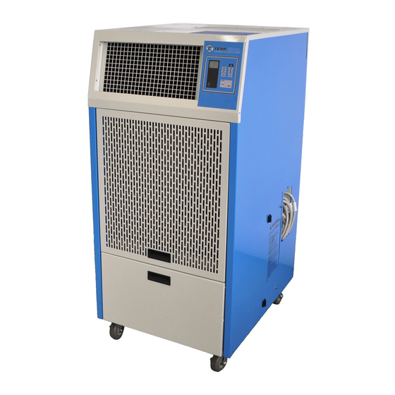
Unit Specifications/Rating Information HIGH PRESSURE SWITCH Specifications TC-18B TC-24B TC-36B TC-60B TC-60B3 TC-60B4 Cooling Capacity, BTU/hr 17,300 29,600 41,000 75,900 75,900 75,900 Power Supply Volts/Ph/Hz/Amps 115/1/60/15 208-230/1/60/20 208-230/1/60/30 208-230/1/60/60 208-230/3/60/40 460/3/60/20 Thermostat Control Electronic Electronic Electronic Electronic Electronic Electronic Metering Device... -
Page 3: Inspection
On the TC-18B but require a tube to be run from the pump to a through TC-36B the high head pressure reset switch can suitable drain. -
Page 4: Optional Features
Determine the proper power by checking the unit’s rat- lows condenser air to be vented to the plenum area above ing plate. For the models from the TC-18B through the a suspended ceiling. TC-36B use the wall outlets and receptacles shown in the table above. -
Page 5: Unit Operation
Portable Cooling Systems TC-60B3 and B4 – 3 Phase Wiring Instructions: or outside location. Do not crimp or bend the tubing, or place it where something might be set on the Only qualified personnel should install TC-60B units. tubing restricting its flow. No portion of the Extra care is required on the three phase units, the TC- discharge tube should be more than 10 feet above the 60B3 and TC-60B4, to insure they are connected in phase... -
Page 6: Ment, Alteration, Service, Or Preventative Maintenance
Do not attempt to clean the filters or operate will flash five times showing the current delay time in the unit without filters. On the TC-18B through TC-36B, hours. If a different time delay is required press the... - Page 7 Portable Cooling Systems ings are lubricated and sealed at the factory, and require no additional lubrication. Dirt on the blower wheels can be cleaned off with a rag. Dirt should not be a problem if the air filters are properly maintained and kept in place. Belt Tension, (TC-60B, 60B3, 60B4 Models only) The condenser fan on the TC-60B series of air condition- ers uses the only blower/motor combination that incor-...
-
Page 8: Troubleshooting Guide
Check for loose or shorted conductors. Secure contact between wires and connectors. Repair or replace as required. Shorted or open run capacitor Replace capacitor. Defective compressor Check for shorts, opens and grounds. Com- pressor replacement should be done by a service technician. TEMP-COOL Owner’s Manual ™... - Page 9 Portable Cooling Systems Problem Cause Remedy Compressor runs but Loose or defective wire Trace and Repair condenser fan does not. Shorted or open condenser motor capacitor. Replace capacitor Insufficient Cooling Bad motor Replace motor Insufficient airflow through evaporator coil due to: - Improper blower rotation (TC-60B3&4) - Check rotation.
-
Page 10: Read Instructions Before Install-Installing Replacement Parts
Remove the motor and blower from the ceiling panel’s framework directly above unit. mounting bracket and attach the new motor and Condensate Pump (TC-18B, 24B, 36B only): blower to it. 1. Unplug unit from power source. Remove condensate d. Reverse the process to complete the process. -
Page 11: Preventative Maintenance
Portable Cooling Systems i. Plug the unit into power and test it in all drop to the bottom of the housing. operating modes; COOL and FAN. 7. Remove the motor mount from the motor and install it on the new motor in the same position as the Condenser Fan Motor, previous motor. -
Page 12: Ing, Operating Or Servicing The Accessories
Accessories Part Description NK-2 two, 6-in nozzles with attachment kit, TC-18B, TC-24B, TC36B NK-3 two, 8-in nozzles with attachment kit, TC-60B, TC-60B3 and TC-60B4 CK-3 14-in ceiling discharge kit, TC-18B, TC-24B, TC-36B CK-4 20-in ceiling discharge kit, TC-60B, TC-60B3 and TC-60B4... -
Page 13: Replacement-Parts List
Portable Cooling Systems Replacement Parts List Description Part Number TC-12B TC-18B TC-24B TC-36B TC-60B TC-60B3 TC-60B4 • service valve, 3/8-in 88400.249 • • • • • • service valve, 1/2-in 88400.250 • service valve, 5/8-in 88400.251 • service valve, 3/4-in 88400.252... - Page 14 Replacement Parts List Description Part Number TC-12B TC-18B TC-24B TC-36B TC-60B TC-60B3 TC-60B4 • 87300.447 • 87300.416 • delay timer 87900.038 • condensate float relay 86300.018 • condensate float relay base 86300.020 • • • • • • • filter door latch 84900.061...
-
Page 15: Wiring Schematic, Tc-12B
Portable Cooling Systems Wiring Schematic, TC-12B... -
Page 16: Wiring Schematic, Tc-18B
Wiring Schematic, TC-18B TEMP-COOL Owner’s Manual ™... -
Page 17: Le Fait De Modifier Ou De Mal Wiring Schematic, Tc-24B
Portable Cooling Systems Wiring Schematic, TC-24B... -
Page 18: Wiring Schematic, Tc-36B
Wiring Schematic, TC-36B TEMP-COOL Owner’s Manual ™... -
Page 19: Entraîner Des Blessures Ou Des Wiring Schematic, Tc-60B
Portable Cooling Systems Wiring Schematic, TC-60B... -
Page 20: Dommages Matériels. On Doit Wiring Schematic, Tc-60B3
Wiring Schematic, TC-60B3 TEMP-COOL Owner’s Manual ™... -
Page 21: Wiring Schematic, Tc-60B4
Portable Cooling Systems Wiring Schematic, TC-60B4... - Page 22 TEMP-AIR 3700 West Preserve Boulevard Burnsville, Minnesota 55337-7746 1-800-836-7432 TC-MAN-BD1 © 2013 TEMP-AIR, Inc. Printed in USA TEMP-COOL Owner’s Manual ™...
Need help?
Do you have a question about the TC-60B4 and is the answer not in the manual?
Questions and answers