Table of Contents
Advertisement
1-800-836-7432
Warning!
Improper installation, adjust-
maintenance can cause injury
or property damage. Please
Avertissement !
installer, régler, réparer ou
entretenir cet appareil peut
lire attentivement les directives
d'installation, d'utilisation et
d'entretien avant de manipuler
l'unité TEMP-COOL
This manual is the property
of the owner. Leave with the
unit when set-up and start-up
are complete. TEMP-AIR
Inc. reserves the right to
change design and specifica-
tions without prior notice.
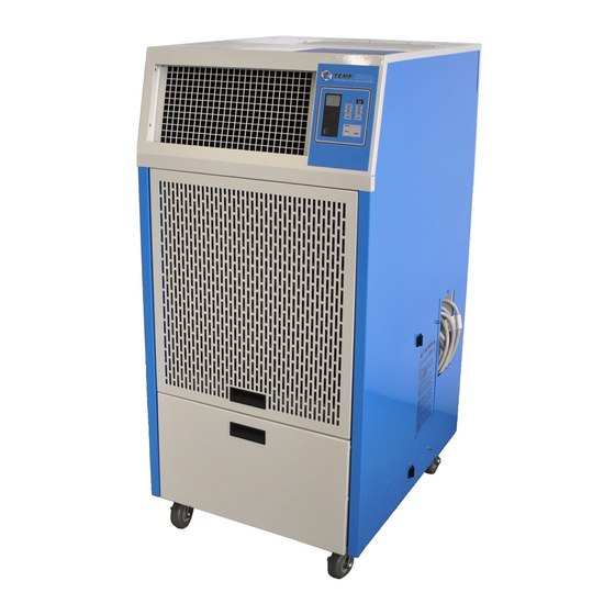
Owner's Manual
Models: TC-12B - TC-60B4, Digital Thermostat
Unit Specifications .......................................................................................... 2
Rating Information ........................................................................................... 2
Inspection ......................................................................................................... 3
General Description ......................................................................................... 3
Standard Features ..........................................................................................3-4
Optional Features ............................................................................................. 4
Installation Instructions .................................................................................4-5
Unit Operation ..............................................................................................5-6
Preventative Maintenance .............................................................................6-7
Troubleshooting Guide .................................................................................8-9
Installing Replacement Parts ....................................................................10-11
Accessories .................................................................................................... 12
Replacement-Parts List .............................................................................13-14
Wiring Schematic, TC-12B ........................................................................... 15
Wiring Schematic, TC-18B ........................................................................... 16
Wiring Schematic, TC-24B ........................................................................... 17
Wiring Schematic, TC-36B ........................................................................... 18
Wiring Schematic, TC-60B ........................................................................... 19
Wiring Schematic, TC-60B3 ......................................................................... 20
Wiring Schematic, TC-60B4 ......................................................................... 21
Advertisement
Table of Contents

Related Manuals for Temp-Cool TC-60B


Summarization of Contents
Unit Inspection and General Description
Serviceability
Details ease of maintenance for filters, tanks, and panels.
High-Pressure Safety Switch
Manual reset switch protects compressor from over-pressure.
Digital Temperature Control System
User selects modes, timers, and has coil freeze protection.
Filters
Describes removable, disposable pleated media filters.
Condensate Tank
5-gallon tank collects moisture, triggers "tF" when full.
Optional Features Overview
Condenser Duct
Allows directing condenser air outside with flexible duct.
Ceiling Panel Duct Kit
Adapts unit for venting condenser air into ceiling plenum.
Discharge Nozzle Kit
Dual-nozzle assembly for precise cool air direction.
Condensate Pump
Drains condensate automatically for continuous operation.
Installation Instructions
Before Installing
Check for damage, save packaging, file claims if necessary.
Electrical Supply Requirements
Determine proper power, check unit rating plate for voltage.
Unit Operation Guide
Placing the Unit
Locate unit on level surface with 18" clearance.
Cooling Operation
Start unit, select Cool mode, adjust setpoint temperature.
Fan Operation
Start unit, select Fan mode, temperature buttons inactive.
Additional Unit Functions
Timer ON/OFF Function
Set unit to turn ON or OFF after a preset period (1-15 hours).
Sleep Mode Operation
Raises setpoint temp 1°F in cooling mode after one hour.
Preventive Maintenance Procedures
Filter Maintenance
Inspect filters every six weeks, replace when dirty.
Coil Cleaning
Clean coils with vacuum then compressed air.
Blowers and Blower Motors
Inspect blowers and motors for cleanliness; no lubrication needed.
Belt Tension Check
Check belt condition, tension, and alignment yearly.
Sheave Adjustment Check
Check sheave setscrews for tightness and alignment.
Troubleshooting Guide
Unit Does Not Run
Covers power issues, thermostat errors, and condensate tank full.
Fan Runs, Compressor/Condenser Do Not
Addresses thermostat issues, start delay, and high-pressure switch.
Compressor Runs, Condenser Fan Does Not
Relates to loose wires or condenser motor capacitor issues.
Insufficient Cooling Issues
Caused by airflow issues, dirty filters, or low refrigerant.
Noisy Operation Troubleshooting
Check blower rotation, loose parts, or motor/bearing issues.
Water Leaks From Pan
Check tank, drain pan, hoses, or pump connections.
Evaporator Coil Freezing
Caused by obstructed airflow or faulty freeze protection.
Installing Accessories and Parts
Ceiling Panel Duct Kit Installation
Secures duct to adapter and ceiling panel for venting.
Condensate Pump Installation (TC-18B, 24B, 36B)
Steps to install pump, remove tank, connect power and hose.
Combination Fan and Blower Replacement
Instructions for replacing the integrated blower/motor package.
Condenser Fan Motor Replacement
Steps to disconnect power, remove panels, and replace motor.
Evaporator Fan Motor Replacement
Steps to remove side panels, disconnect wiring, and replace motor.
Wiring Schematics
Wiring Schematic for TC-12B
Provides a detailed electrical diagram for the TC-12B model.
Wiring Schematic for TC-18B
Provides a detailed electrical diagram for the TC-18B model.
Wiring Schematic for TC-24B
Provides a detailed electrical diagram for the TC-24B model.
Wiring Schematic for TC-36B
Provides a detailed electrical diagram for the TC-36B model.
Wiring Schematic for TC-60B
Provides a detailed electrical diagram for the TC-60B model.
Wiring Schematic for TC-60B3
Provides a detailed electrical diagram for the TC-60B3 model.
Wiring Schematic for TC-60B4
Provides a detailed electrical diagram for the TC-60B4 model.
Need help?
Do you have a question about the TC-60B and is the answer not in the manual?
Questions and answers