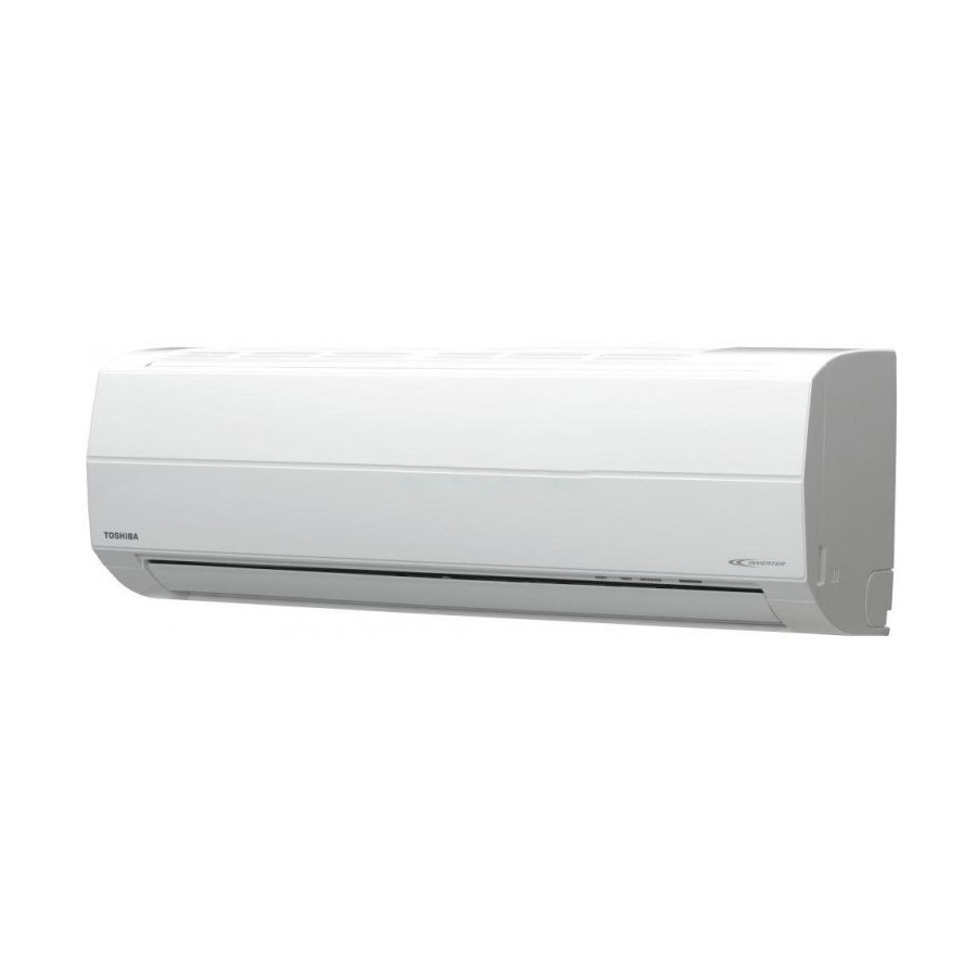
Summarization of Contents
2. SPECIFICATIONS
Product Specifications Overview
Detailed technical specifications for various models and components.
RAS-16SKV2-E Specifications
Technical specifications for the RAS-16SKV2-E model.
Operation Characteristic Curves
Performance curves illustrating operational characteristics.
Capacity Variation by Temperature
Graphs showing how capacity changes with outdoor temperature.
3. REFRIGERANT R410A
Installation and Servicing Safety
Safety precautions for installing and servicing with R410A refrigerant.
Refrigerant Piping Installation
Guidelines for installing refrigerant piping systems.
Required Tools
Lists tools required for R410A systems and their interchangeability.
Recharging of Refrigerant
Step-by-step procedure for recharging refrigerant.
3-5. Brazing of Pipes
Brazing Materials
Details different types of brazing filler materials used.
Flux Requirements
Explains the necessity and types of flux for brazing.
Brazing Procedure
Details the brazing process, including oxidation prevention methods.
4. CONSTRUCTION VIEWS
Indoor Unit Construction
Explains the construction and dimensions of the indoor unit.
Outdoor Unit Construction
Details the construction and dimensions of the outdoor unit.
5. WIRING DIAGRAM
Wiring for RAS-10/13SKV2-E and RAS-10/13SAV2-E
Wiring diagram for specific indoor and outdoor unit models.
Wiring for RAS-16SKV2-E and RAS-16SAV2-E
Wiring diagram for the RAS-16SKV2-E and RAS-16SAV2-E models.
6. SPECIFICATIONS OF ELECTRICAL PARTS
Indoor Unit Electrical Parts
Lists electrical components and specifications for the indoor unit.
Outdoor Unit Electrical Parts
Lists electrical components and specifications for the outdoor unit.
7. REFRIGERANT CYCLE DIAGRAM
Refrigerant Cycle Diagrams
Illustrates the refrigerant flow for different unit models.
Operation Data Tables
Provides cooling and heating operation data for various conditions.
8. CONTROL BLOCK DIAGRAM
Indoor Unit Control Block Diagram
Details the control logic and components of the indoor unit.
Outdoor Unit Control Block Diagram
Explains the control logic and components of the outdoor unit inverter assembly.
9. OPERATION DESCRIPTION
Air Conditioner Control Overview
Explains the overall control system of the air conditioner.
9-2. Operation Description
Detailed Operation Modes
Details various operational modes like Basic, Cooling, AUTO, DRY, ECO, etc.
9-3. Auto Restart Function
Setting the Auto Restart Function
Steps to enable the auto restart feature.
Cancelling Auto Restart and Timer Issues
Procedures for cancelling auto restart and handling timer failures.
9-4. Remote Controller and Its Functions
Remote Controller Parts Identification
Identifies the buttons and features of the remote controller.
Remote Control Operations
Explains how to use various remote control functions like ONE-TOUCH and AUTO.
Remote Controller Display Indications
Explains the meaning of various indicators on the remote controller display.
10. INSTALLATION PROCEDURE
Installation Diagrams and Parts
Illustrates unit placement, connection, and lists optional parts.
10-2. Installation Details
Installation Tools and Guidelines
Covers general installation, bolts, and tools.
10-3. Indoor Unit Installation
Indoor Unit Installation Location and Mounting
Guidelines for selecting location and mounting the installation plate.
Indoor Unit Electrical Work and Wiring
Procedures for electrical connections and wiring the indoor unit.
10-4. Outdoor Unit Installation
Outdoor Unit Location, Draining, and Piping
Covers unit placement, draining, and refrigerant pipe connection.
Evacuating and Wiring Connection
Procedures for system evacuation and connecting electrical wiring.
10-5. Test Operation
Gas Leak Test and System Test
Performing gas leak checks and initial system operation tests.
Controller Settings and Auto Restart
Configuring remote controller selection and auto restart function.
11. HOW TO DIAGNOSE THE TROUBLE
Initial Checks and Self-Diagnosis
Performing initial confirmations, primary judgments, and remote controller self-diagnosis.
Symptom-Based Troubleshooting
Diagnosing troubles based on symptoms for indoor unit and wiring.
Component Checking Procedures
Procedures for checking main parts, outdoor unit, P.C. boards, and fan motor.
12. HOW TO REPLACE THE MAIN PARTS
Indoor Unit Part Replacement
Procedures for replacing indoor unit parts like front panel, electric box, motor, and microcomputer.
Outdoor Unit Part Replacement
Procedures for detaching and attaching outdoor unit components like cabinets and covers.
13. EXPLODED VIEWS AND PARTS LIST
Indoor Unit (Part-E) Exploded View and List
Provides an exploded view and list of parts for the indoor unit (Part-E).
Indoor Unit Components Exploded View
Shows an exploded view of various indoor unit components and their parts.
Outdoor Unit Exploded View and Parts List
Provides an exploded view and list of parts for the outdoor unit.


Need help?
Do you have a question about the RAS-10SKV2-E and is the answer not in the manual?
Questions and answers