Table of Contents
Advertisement
Advertisement
Table of Contents

Related Manuals for MORLEY-IAS ZX2Se


Summarization of Contents
Introduction
1.1 Notice
Manual accuracy, modification rights, and manufacturer disclaimer.
1.2 Warnings and Cautions
Safety procedures to avoid injury and equipment damage.
1.3 National Approvals
Installation and operation according to national, regional, and local regulations.
User Control Levels
2.1 Level Definition
Explains the three user control levels: Level 1 (display only), Level 2 (operation), Level 3 (installer).
2.2 User Passwords
Details programming, assignment, and limitations of user passwords for access levels.
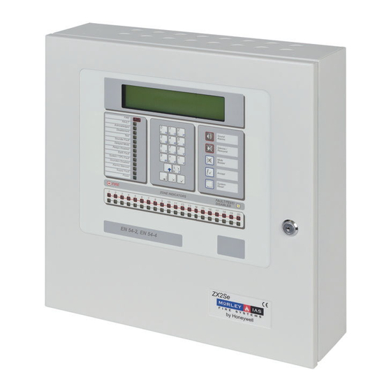
Controls and Displays
3.1 Control keys
Description of system control and alphanumeric keys and their functions.
3.2 Front Panel LED Indications
Explains the meaning of the LED indicators for panel status and zone alarms.
3.3 Alphanumeric Display Indications
Details information shown on the alphanumeric display, including normal, fire, and fault conditions.
Level 1 Display / Control Functions
4.1 Normal Conditions
Panel status when no alarms or faults are present, showing time and system messages.
4.2 AC Mains Power Fail Conditions
Panel behavior during AC power interruption, including LED and buzzer indications.
4.3 Fire Alarm Conditions
Indication of fire alarms, including LED, buzzer, and display information.
4.3.1 Override Delays
How to override delays using a manual call point for immediate alarm activation.
4.4 Fault Conditions
Panel indication of faults, including LED, buzzer, and display details.
Level 2 Control Functions
5.1 Power Failure Condition
Details AC mains and battery power failure indications and actions.
5.1.1 AC Mains Power Failure Indication
Indication of AC mains power loss, including LED, buzzer, and display messages.
5.1.2 Battery Low / Charger Failure
Indication of battery issues or charger failure with corresponding messages.
5.2 Fault Conditions
How the panel indicates and handles fault conditions.
5.2.1 Fault Indication
Details the FAULT LED and alphanumeric display for fault information.
5.2.2 User Actions
User actions to acknowledge, silence, and reset fault conditions.
5.3 Fire Alarm Conditions
Panel indication and handling of fire alarm conditions.
5.3.1 Fire Alarm Indications
How fire alarms are displayed, including FIRE LED and zone indicators.
5.3.2 User Actions
User actions for fire alarms, including silencing and resetting.
5.4 User Option Functions
Overview of optional functions available at Level 2, including Test, Time, Enable/Disable, Print, View.
5.4.1 Test
Menu options for testing system components like LEDs, LCD, Zones, and Outputs.
5.4.1.1 LED Test
Procedure to test all panel LED indicators, including zone indicators.
5.4.1.2 LCD Test
Procedure to test the alphanumeric display by flashing all characters.
5.4.1.3 Zones Test
Procedure for performing a 'Walk Test' on selected zones.
5.4.1.3.1 Configuring the Test
Setting up the Walk Test, including sounder options and zone range.
5.4.1.3.2 Terminating the Test
How to exit the Walk Test mode and the panel's behavior upon termination.
5.4.1.3.3 Inspecting Other Conditions During a Walk Test
How to view Fire, Fault, or Disablement conditions during a walk test.
5.4.1.4 Output Test
Testing of onboard relay and sounder outputs, requiring Level 3 password.
5.4.1.5 Audible Indicator Test
Procedure to test the internal buzzer, which will beep once.
5.4.2 Time
How to change the date and time on the panel.
5.4.3 Enable / Disable Functions
Menu to enable or disable zones, inputs, outputs, keys, and day modes.
5.4.3.1 Enable or Disable Zones
Process to enable or disable input devices within a specific zone.
5.4.3.2 Enable or Disable Inputs
Process to enable or disable individual input devices by loop and address.
5.4.3.3 Enable or Disable Keys
Disabling panel control keys and re-enabling them with Level 2 password.
5.4.3.4 Enable or Disable Delayed Day Modes
Configuration and management of delayed day mode operations.
Log Book
REFERENCE DATA
Section for recording site details, installation, and maintenance information.
EVENT DATA
Template for recording specific events, actions, and completion details in the log.
Need help?
Do you have a question about the ZX2Se and is the answer not in the manual?
Questions and answers