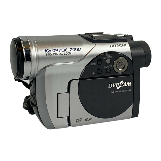
Hitachi MV730A - DZ Camcorder - 680 KP Service Manual
Dvd video camera/recorder
Hide thumbs
Also See for MV730A - DZ Camcorder - 680 KP:
- Instruction manual (190 pages) ,
- Instruction manual (190 pages)
Table of Contents
Advertisement
Quick Links
Download this manual
See also:
Instruction Manual
SERVICE MANUAL
DZ-GX20A
During the product warranty period, please contact
1.800.HITACHI (800.448.2244) for guidance.
SPECIFICATIONS AND PARTS ARE SUBJECT TO CHANGE FOR IMPROVEMENT
DVD VIDEO CAMERA/RECORDER
February
Version 0502E.1
DZ-MV780A
DZ-MV730A
2005
Digital Media Division,Tokai
TK
No. 0502E
DZ-GX20A
DZ-MV780A
DZ-MV730A
Change 1
DO NOT RESELL OR DIVERT IMPROPERLY
Advertisement
Table of Contents
Troubleshooting

Summarization of Contents
Safety Precaution for Repair
1-1 Cautions
General cautions for handling lithium batteries, laser products, and high-voltage components.
1-2 Electrostatic Protection Measures
Measures to prevent static damage to components during servicing.
1-3 Cautions When Handling DVD Drive
Precautions for handling the high-precision DVD drive to avoid damage.
1-4 Lead-Free Solder
Information and cautions regarding the use of lead-free solder and soldering iron temperatures.
1-5 Notes When Using Service Manual
Explanation of units used in parts lists and abbreviations in schematic diagrams.
General Description
2-1 Overview
Overview of the camera models and their key specifications.
2-2 Features
Key features of the DVD video cameras, including recording quality and compatibility.
2-3 Specifications
Detailed technical specifications for each camera model.
2-4 Major Differences from Previous Models
Comparison of current models with previous versions regarding dimensions and features.
2-5 Compatibility of Recorded Discs
Information on DVD-RAM and DVD-R disc compatibility.
2-6 Names of Parts
Identification of external parts and accessories of the DVD video camera/recorder.
2-7 List of Abbreviations and Terms for DVD Video Camera/Recorders
Definitions of technical terms and abbreviations used in the manual.
Description of Operation
3-1 Description of Structure
Details structural differences between camera models and circuit board configurations.
3-2 Description of Newly Adapted Technology
Explanation of new technologies like Assist Light and Quick Start functions.
Troubleshooting
4-1 Procedure for Troubleshooting
Outlines the systematic procedure for troubleshooting issues encountered with the device.
4-2 Problem Guide
Guide to common symptoms, causes, and corrections for camera malfunctions.
4-3 Messages and Troubleshooting
Lists displayed messages and their corresponding troubleshooting actions.
4-4 Display of Error Codes and Troubleshooting
How to display and clear error codes and their major troubleshooting.
4-5 Checking Versions of Firmware and Updating
Process for checking and updating firmware versions for performance improvement.
4-6 Trouble Diagnosis
Flowcharts and methods for diagnosing internal component issues.
4-7 Procedure for Removing Disc from Faulty DVD Video Camera/Recorder
Step-by-step guide for safely removing a disc from a malfunctioning unit.
4-8 System Resetting/Resetting Camera Functions
Procedures for system reset and resetting camera functions to default settings.
4-9 Special Functions
Details special functions like forced DVD-RAM initialization and EEPROM backup.
Disassembly and Reassembly
5-1 Items to Be Checked
Pre-disassembly checks for discs, cards, and safety precautions.
5-2 Order of Disassembly
General order of component removal and disassembly flowcharts.
5-3 Disassembly
Step-by-step instructions for disassembling various camera components.
Adjustment
6-1 Creating Reference Data
Process for creating reference data essential for accurate adjustments.
6-2 Setups for Adjustment
Procedures for checking reference data needs, setting up test equipment, and connections.
6-3 List of Adjustment Items
Overview of adjustment items, their purpose, and required components.
6-4 Adjustment Procedure
Step-by-step guides for performing specific adjustments like Video Level and Autofocus.
Exploded View
7-1 Exploded Views
Provides an exploded view of the main components for DZ-GX20A/MV730A.
7-1-1 DZ-GX20A/MV730A Main
Exploded view of the main assembly for DZ-GX20A/MV730A.
7-1-2 DZ-GX20A Camera
Exploded view showing specific camera parts for the DZ-GX20A model.
7-1-3 DZ-MV730A Camera
Exploded view showing specific camera parts for the DZ-MV730A model.
7-1-4 DZ-MV780A
Exploded view showing specific camera parts for the DZ-MV780A model.
Schematic & Wiring Diagrams
S-1 DZ-GX20A/MV730A Wiring Diagram
Wiring diagram for DZ-GX20A/MV730A models.
S-2 DZ-MV780A Wiring Diagram
Wiring diagram for the DZ-MV780A model.
S-3 GSL-H
Schematic diagram for the GSL-H circuit board.
S-4 GSL-M
Schematic diagram for the GSL-M circuit board.
S-5 GSL-L
Schematic diagram for the GSL-L circuit board.
S-6 FRT-H/FRT-M/FRT-L
Schematic diagram for the FRT circuit boards.
S-7 AVJ-H/AVJ-M/AVJ-L
Schematic diagram for the AVJ circuit boards.
S-8 SHE-H
Schematic diagram for the SHE-H circuit board.
S-9 SHE-M
Schematic diagram for the SHE-M circuit board.
S-10 DRF-H/DRF-M/DRF-L
Schematic diagram for the DRF circuit boards.
S-11 AEL
Schematic diagram for the AEL circuit board.
S-12 CAMERA DSP [MAN]
Schematic diagram for the CAMERA DSP [MAN] circuit board.
S-13 CODEC [MAN]
Schematic diagram for the CODEC [MAN] circuit board.
S-14 REG [MAN]
Schematic diagram for the REG [MAN] circuit board.
S-15 PLUG [MAN]
Schematic diagram for the PLUG [MAN] connector.
S-16 LENS DRIVE [MAN]
Schematic diagram for the LENS DRIVE [MAN] circuit board.
S-17 IC Block Diagrams-1/2
Block diagrams of integrated circuit components, part 1.
S-18 IC Block Diagrams-2/2
Block diagrams of integrated circuit components, part 2.
Circuit Board Diagrams
C-1 GSL-H
Circuit board diagram for the GSL-H board.
C-2 GSL-M
Circuit board diagram for the GSL-M board.
C-3 GSL-L
Circuit board diagram for the GSL-L board.
C-4 FRT-H/FRT-M/FRT-L
Circuit board diagram for the FRT boards.
C-5 AVJ-H/AVJ-M/AVJ-L
Circuit board diagram for the AVJ boards.
C-6 DRF-H/DRF-M/DRF-L
Circuit board diagram for the DRF boards.
C-7 SHE-H
Circuit board diagram for the SHE-H board.
C-8 SHE-M
Circuit board diagram for the SHE-M board.
C-9 AEL [Pattern No.JA2296-7]
Circuit board diagram for the AEL board (Pattern No.JA2296-7).
C-10 AEL [Pattern No.JA2296-8]
Circuit board diagram for the AEL board (Pattern No.JA2296-8).
C-11 MAN
Circuit board diagram for the MAN board.
Block Diagrams
B-1 Video/Audio Signal Process
Block diagram illustrating the video and audio signal processing flow.
B-2 Power-1
Block diagram illustrating the power supply system, part 1.
B-3 Power-2
Block diagram illustrating the power supply system, part 2.


Need help?
Do you have a question about the MV730A - DZ Camcorder - 680 KP and is the answer not in the manual?
Questions and answers