Table of Contents
Advertisement
CONTENTS
CS-E9EKEB CU-E9EKEB
CS-E12EKEB CU-E12EKEB
Page
3
5
5
7
9
9
9
9
9
10
10
10
10
11
11
12
© 2005 Panasonic HA Air-Conditioning (M) Sdn Bhd
(11969-T). All rights reserved. Unauthorized copying
and distribution is a violation of law.
Order No: MAC0510072C2
Air Conditioner
Page
13
14
15
15
16
17
17
19
21
21
22
23
23
24
27
Advertisement
Table of Contents

Summarization of Contents
Service Manual Air Conditioner
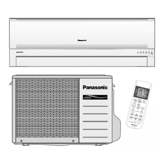
Model Identification: CS-E9EKEB / CS-E12EKEB CU-E9EKEB / CU-E12EKEB
Identifies the specific air conditioner models covered by the manual.
Safety Precautions
General Warnings and Cautions
Critical safety guidelines for handling and servicing the unit.
Installation Safety Requirements
Essential safety rules for proper unit installation.
Specifications
CS-E9EKEB CU-E9EKEB Model Specifications
Detailed technical specifications for CS-E9EKEB CU-E9EKEB models.
Specifications (Continued)
CS-E12EKEB CU-E12EKEB Model Specifications
Detailed technical specifications for CS-E12EKEB CU-E12EKEB models.
Key Features
Air Purification and Quiet Operation
Describes air purifying systems, ionizer, and quiet mode features.
Energy Efficiency and Heating Performance
Highlights energy efficiency and powerful heating capabilities.
Component Locations
Indoor/Outdoor Unit Controls and Components
Identifies controls and components on the indoor and outdoor units.
Remote Control Layout and Functions
Visual guide to the remote control's buttons and display.
Dimensions and Installation Planning
Indoor Unit and Remote Control Dimensions
Provides physical dimensions and mounting details for the indoor unit.
Dimensions and Installation Planning (Continued)
Outdoor Unit Dimensions and Space Requirements
Specifies the physical size and necessary clearance for the outdoor unit.
Wiring Diagrams
CS-C9EKEB / CS-C12EKEB Wiring Schematic
Detailed electrical wiring diagram for specific models.
Wiring Diagrams (Continued)
CU-C9EKEB / CU-C12EKEB Wiring Schematic
Detailed electrical wiring diagram for specific models.
Printed Circuit Board Layouts
Indoor Unit PCB Layout and Identification
Visual representation of the indoor unit's main circuit board.
Printed Circuit Board Layouts (Continued)
Outdoor Unit PCB Layout and Identification
Visual representation of the outdoor unit's main circuit board.
Simplified Electronic Circuit Diagrams
Indoor Unit Simplified Circuit Diagram
Simplified electronic schematic for the indoor unit's operation.
Simplified Electronic Circuit Diagrams (Continued)
Outdoor Unit Simplified Circuit Diagram
Simplified electronic schematic for the outdoor unit's operation.
Installation Procedures
Selecting the Optimal Installation Location
Guidance on choosing the best placement for indoor and outdoor units.
Installation Procedures (Continued)
Indoor Unit Mounting and Hole Preparation
Steps for attaching the mounting plate and drilling wall openings.
Indoor Unit Piping and Cable Connection
Procedures for connecting piping and electrical cables to the indoor unit.
Installation Procedures (Continued)
Indoor Unit Piping, Insulation, and Cable Securing
Detailed steps for insulating pipes and securing cables.
Installation Procedures (Continued)
Outdoor Unit Installation and Piping Connection
Instructions for mounting the outdoor unit and flaring/connecting pipes.
Installation Procedures (Continued)
Equipment Evacuation Procedure
Critical steps for removing air and moisture from the refrigeration system.
Outdoor Unit Electrical Connection
Guidelines for connecting the power cable to the outdoor unit.
Installation Procedures (Continued)
Pipe Insulation and Drainage Verification
Methods for insulating pipes and checking the drain system.
Post-Installation Performance Check
Procedures to evaluate unit operation after installation.
Operation and Control
Basic Functions and Temperature Settings
Explains inverter control, internal temperature adjustments, and modes.
Airflow Direction Adjustment
How to adjust vertical and horizontal airflow directions.
Operation and Control (Continued)
Quiet Operation Modes and Settings
Details on activating and controlling quiet operation for cooling and heating.
Operation and Control (Continued)
Powerful Mode and Timer Functions
Using powerful mode for rapid cooling/heating and setting timers.
Operation and Control (Continued)
Auto Restart and Ionizer Operation
How auto restart works and the operation of the ionizer.
Protection Controls
Compressor and Power Protection Mechanisms
Safety features protecting the compressor and power transistors.
Protection Controls (Continued)
Operational Anomaly Protection Measures
Protections against four-way valve issues, freezing, and temperature limits.
Servicing Mode Operations
Auto Switch Functions and Indicator Lights
How to use the auto switch for test runs and understand indicator lights.
Troubleshooting Guide
Refrigeration Cycle Diagnosis and Measurement
Steps to diagnose problems by analyzing the refrigeration cycle.
Troubleshooting Guide (Continued)
Breakdown Self-Diagnosis Function
Procedure for accessing and interpreting unit error codes.
Troubleshooting Guide (Continued)
Comprehensive Error Codes Table
A detailed list of error codes, their causes, and troubleshooting locations.
Disassembly and Assembly Instructions
Indoor Electronic Controller Removal Procedure
Step-by-step guide to remove the indoor unit's main control board.
Disassembly and Assembly Instructions (Continued)
Indoor Fan and Motor Disassembly
Instructions for removing the indoor unit's fan and motor.
Disassembly and Assembly Instructions (Continued)
Outdoor Fan and Motor Disassembly
Procedures for removing the outdoor unit's fan and motor assembly.
Technical Data
CS-E9EKEB CU-E9EKEB Cooling Performance
Graphs showing cooling capacity and current vs. outdoor temperature.
Technical Data (Continued)
CS-E9EKEB CU-E9EKEB Heating Performance
Graphs showing heating capacity vs. outdoor temperature.
Technical Data (Continued)
CS-E9EKEB CU-E9EKEB Piping Length Performance
Charts illustrating performance variations with different pipe lengths.
Technical Data (Continued)
CS-E12EKEB CU-E12EKEB Cooling Performance
Graphs for cooling performance of E12 models against outdoor temperature.
Technical Data (Continued)
CS-E12EKEB CU-E12EKEB Heating Performance
Graphs for heating performance of E12 models against outdoor temperature.
Technical Data (Continued)
CS-E12EKEB CU-E12EKEB Piping Length Performance
Charts showing performance variations for E12 models based on pipe length.
Technical Data (Continued)
Sensible Capacity Chart
Table providing sensible heat capacity data under specific conditions.
Exploded Views and Parts Lists
CS-E9EKEB CS-E12EKEB Indoor Unit Exploded View
Visual breakdown of the indoor unit's components for identification.
Exploded Views and Parts Lists (Continued)
CS-E9EKEB CS-E12EKEB Replacement Parts List
Catalog of part numbers for CS-E9EKEB CS-E12EKEB indoor units.
Exploded Views and Parts Lists (Continued)
CU-E9EKEB CU-E12EKEB Outdoor Unit Exploded View
Visual breakdown of the outdoor unit's components for identification.
Exploded Views and Parts Lists (Continued)
CU-E9EKEB CU-E12EKEB Replacement Parts List
Catalog of part numbers for CU-E9EKEB CU-E12EKEB outdoor units.


Need help?
Do you have a question about the CS-E12EKEB and is the answer not in the manual?
Questions and answers