Advertisement
Table of Contents
- 1 Revision History
- 2 Service Note
- 3 Self-Diagnosis Function
- 4 Self-Diagnosis Code Table
- 5 Power Supply During Repairs
- 6 Method of Coping with Shift Lens Error
- 7 Repair Parts List
- 8 Identifying Parts
- 9 Note for Repair
- 10 Disassembly
- 11 Main Board Section Exploded View
- 12 BT/EVF SECTION Exploded View
- 13 Lcd Section Exploded View
- 14 Block Diagrams
- 15 Control Switch Block
- 16 Flash Unit
- Download this manual
HDR-CX550/CX550E/CX550V/CX550VE/
SERVICE MANUAL
Ver. 1.0 2010.01
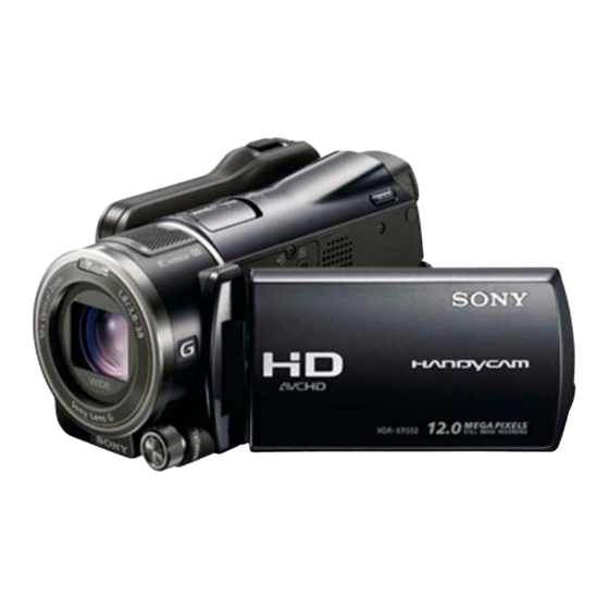
Photo: HDR-XR550
SERVICE NOTE (Check the following note before the service.)
1-1. POWER SUPPLY DURING REPAIRS
1-2. PRECAUTION ON REPLACING THE VC-592 BOARD
1-3. PRECAUTION ON REPLACING THE MM-094 BOARD
1-4. SELF-DIAGNOSIS FUNCTION
1-5. METHOD OF COPING WITH SHIFT LENS ERROR
1-6. PRECAUTION ON REPLACING THE CABINET (BM)
1-7. GPS RECEIVING CHECK(CX550V/CX550VE/XR550V/XR550VE)
1-8. PRECAUTION ON REPLACING THE HDD(XR550V/XR550VE),
DD-329 BOARD (CX550V/CX550VE)
DIGITAL HD VIDEO CAMERA RECORDER
The components identified
Les composants identifiés par
by mark 0 or dotted line with
une marque 0 sont critiques
mark 0 are critical for safety.
pour la sécurité.
Replace only with part number
Ne les remplacer que par une
specified.
pièce portant le numéro spécifié.
HDR-CX550/CX550E/CX550V/CX550VE/XR550/XR550E/XR550V/XR550VE_L2
9-852-777-31
XR550/XR550E/XR550V/XR550VE
Canadian Model
North European Model
Australian Model
Hong Kong Model
Chinese Model
Korea Model
Tourist Model
Japanese Model
RMT-835
Ver.
Date
2
LEVEL
1.0
2010.01
US Model
AEP Model
E Model
Sony EMCS Co.
Revision History
History
Contents
Official Release
—
985277731.pdf
S.M. Rev.
issued
—
2010A0800-1
© 2010.01
Published by Tokai TEC
Advertisement
Table of Contents

Summarization of Contents
SERVICE NOTE
1-1. POWER SUPPLY DURING REPAIRS
Procedure for ensuring continuous power supply during repair work.
1-2. PRECAUTION ON REPLACING THE VC-592 BOARD
Important precautions before replacing the VC-592 board.
1-3. PRECAUTION ON REPLACING THE MM-094 BOARD
Important precautions before replacing the MM-094 board.
1-4. SELF-DIAGNOSIS FUNCTION
Functionality and display of the unit's self-diagnosis system.
1-5. METHOD OF COPING WITH SHIFT LENS ERROR
Steps to resolve shift lens errors and related issues.
1-6. PRECAUTION ON REPLACING THE CABINET (BM)
Guidelines for replacing the unit's cabinet (BM).
1-7. GPS RECEIVING CHECK (CX550V/CX550VE/XR550V/XR550VE)
Procedure to check GPS signal reception and functionality.
1-8. PRECAUTION ON REPLACING THE HDD (XR550V/XR550VE), DD-329 BOARD (CX550V/CX550VE)
Precautions for replacing HDD and DD-329 board.
SAFETY-RELATED COMPONENT WARNING!!
SAFETY CHECK-OUT
Essential safety checks to perform after repair before customer release.
2. REPAIR PARTS LIST
IDENTIFYING PARTS
Guide to identifying and locating parts in exploded views and parts lists.
DISASSEMBLY
Instructions and procedures for disassembling the camcorder unit.
2-1. EXPLODED VIEWS
2-1-1. OVERALL SECTION-1
Exploded view of the overall camcorder section 1 for specific models.
DISASSEMBLY
Steps for disassembling the camcorder as shown in the exploded view.
3. ASSEMBLY
Assembly-1: The Method of attachment of FP-1208 Flexible Board
Step-by-step guide for attaching the FP-1208 flexible board.
Assembly-2: How to Fold the Microphone Flexible Board
Instructions on properly folding the microphone flexible board.
4. BLOCK DIAGRAMS
4-1. OVERALL BLOCK DIAGRAM (1/2)
First part of the overall block diagram of the camcorder system.
5. FRAME SCHEMATIC DIAGRAMS
5-1. FRAME SCHEMATIC DIAGRAM (1/2)
First part of the frame schematic diagrams illustrating the camcorder's structure.
6. SCHEMATIC DIAGRAMS AND PRINTED WIRING BOARDS
6-1. SCHEMATIC DIAGRAMS
Detailed schematic diagrams of the camcorder's electronic circuits.


Need help?
Do you have a question about the Handycam HDR-XR550VE and is the answer not in the manual?
Questions and answers