Advertisement
Table of Contents
- 1 Revision History
- 2 Service Note
- 3 Self-Diagnosis Function
- 4 Self-Diagnosis Code Table
- 5 Power Supply During Repairs
- 6 Method of Coping with Shift Lens Error
- 7 Repair Parts List
- 8 Identifying Parts
- 9 Note for Repair
- 10 Disassembly
- 11 Main Board Section Exploded View
- 12 BT/EVF SECTION Exploded View
- 13 Lcd Section Exploded View
- 14 Block Diagrams
- 15 Control Switch Block
- 16 Flash Unit
- Download this manual
HDR-CX550/CX550E/CX550V/CX550VE/
SERVICE MANUAL
Ver. 1.0 2010.01
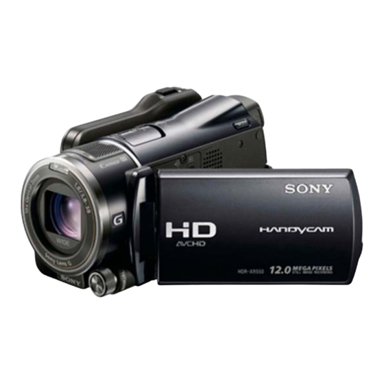
Photo: HDR-XR550
SERVICE NOTE (Check the following note before the service.)
1-1. POWER SUPPLY DURING REPAIRS
1-2. PRECAUTION ON REPLACING THE VC-592 BOARD
1-3. PRECAUTION ON REPLACING THE MM-094 BOARD
1-4. SELF-DIAGNOSIS FUNCTION
1-5. METHOD OF COPING WITH SHIFT LENS ERROR
1-6. PRECAUTION ON REPLACING THE CABINET (BM)
1-7. GPS RECEIVING CHECK(CX550V/CX550VE/XR550V/XR550VE)
1-8. PRECAUTION ON REPLACING THE HDD(XR550V/XR550VE),
DD-329 BOARD (CX550V/CX550VE)
DIGITAL HD VIDEO CAMERA RECORDER
The components identified
Les composants identifiés par
by mark 0 or dotted line with
une marque 0 sont critiques
mark 0 are critical for safety.
pour la sécurité.
Replace only with part number
Ne les remplacer que par une
specified.
pièce portant le numéro spécifié.
HDR-CX550/CX550E/CX550V/CX550VE/XR550/XR550E/XR550V/XR550VE_L2
9-852-777-31
XR550/XR550E/XR550V/XR550VE
Canadian Model
North European Model
Australian Model
Hong Kong Model
Chinese Model
Korea Model
Tourist Model
Japanese Model
RMT-835
Ver.
Date
2
LEVEL
1.0
2010.01
US Model
AEP Model
E Model
Sony EMCS Co.
Revision History
History
Contents
Official Release
—
985277731.pdf
S.M. Rev.
issued
—
2010A0800-1
© 2010.01
Published by Tokai TEC
Advertisement
Table of Contents

Related Manuals for Sony Handycam HDR-XR550E


Summarization of Contents
SERVICE MANUAL
Revision History
Records changes made to the service manual.
SERVICE NOTE
Important notes to check before performing service.
SERVICE NOTE
1-1. POWER SUPPLY DURING REPAIRS
Method to prevent power shut-off during repair.
1-2. PRECAUTION ON REPLACING THE VC-592 BOARD
Precautions for replacing VC-592 board, including data handling.
1-3. PRECAUTION ON REPLACING THE MM-094 BOARD
Precautions for replacing MM-094 board, focusing on sensor adjustment.
1-4. SELF-DIAGNOSIS FUNCTION
Explanation of the self-diagnosis function and error codes.
1-6. PRECAUTION ON REPLACING THE CABINET (BM)
1-6-1. Precaution on ordering the Cabinet (BM)
Guidelines for ordering replacement cabinets based on model.
2. REPAIR PARTS LIST
IDENTIFYING PARTS
Instructions for identifying and referencing parts in exploded views.
DISCHARGING OF THE ST-230 BOARD'S CHARGING CAPACITOR (C5012)
Preparing the Short Jig
Instructions for creating a short jig for capacitor discharge.
2-1. EXPLODED VIEWS
2-1-1. OVERALL SECTION-1
Exploded view of the overall XR series section 1.
DISASSEMBLY
Step-by-step instructions for disassembling the unit.
2-1-2. OVERALL SECTION-1
DISASSEMBLY
Step-by-step instructions for disassembly.
2-1-3. OVERALL SECTION-2
DISASSEMBLY
Step-by-step instructions for disassembly.
2-1-4. OVERALL SECTION-2
DISASSEMBLY
Step-by-step instructions for disassembly.
2-1-5. SHOE COVER SECTION
DISASSEMBLY
Step-by-step instructions for disassembly.
3. ASSEMBLY
Assembly-1: The Method of attachment of FP-1208 Flexible Board
Steps to attach the FP-1208 flexible board.
Assembly-2: How to Fold the Microphone Flexible Board
Instructions for folding the microphone flexible board.
4. BLOCK DIAGRAMS
4-1. OVERALL BLOCK DIAGRAM (1/2)
First part of the overall block diagram.
5. FRAME SCHEMATIC DIAGRAMS
5-1. FRAME SCHEMATIC DIAGRAM (1/2)
First part of the frame schematic diagram.
SCHEMATIC DIAGRAMS AND PRINTED WIRING BOARDS
For Schematic Diagrams
Notes specific to schematic diagrams.
For Printed Wiring Boards
Notes specific to printed wiring boards.
Precautions for Replacement of Imager
Important precautions when replacing the imager.
Need help?
Do you have a question about the Handycam HDR-XR550E and is the answer not in the manual?
Questions and answers