Table of Contents
Advertisement
SERVICE MANUAL
Ver. 1.1 2009.02
Revision History
Revision History
Revised-1
Replace the previously issued
SERVICE MANUAL 9-852-642-31
with this manual.
Link
Link
SPECIFICATIONS
MODEL INFORMATION TABLE
SERVICE NOTE
• Precaution on Replacing the VC-559 Board
The components identified by
mark 0 or dotted line with
mark 0 are critical for safety.
Replace only with part num-
ber specified.
HDR-CX100/CX100E/CX105E/CX106E/CX120_L2
9-852-642-32
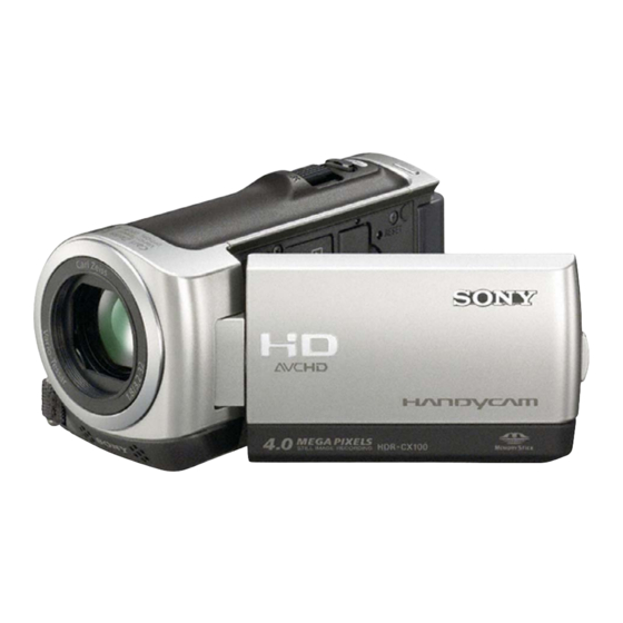
Photo: HDR-CX100
DISASSEMBLY
BLOCK DIAGRAMS
FRAME SCHEMATIC DIAGRAM
Les composants identifiés par une
marque 0 sont critiques pour la
sécurité.
Ne les remplacer que par une pièce
portant le numéro spécifié.
DIGITAL HD VIDEO CAMERA RECORDER
Sony EMCS Co.
HDR-CX100/CX100E/CX105E/
CX106E/CX120
LEVEL
US Model
Canadian Model
AEP Model
UK Model
North European Model
E Model
Australian Model
Hong Kong Model
Chinese Model
Korea Model
Tourist Model
Japanese Model
SCHEMATIC DIAGRAMS
PRINTED WIRING BOARDS
REPAIR PARTS LIST
Published by Kohda TEC
2
2009B0500-1
© 2009.2
Advertisement
Table of Contents

Related Manuals for Sony HDR-CX120


Summarization of Contents
Specifications
System Details
Details on signal format, recording format, media, image device, and lens.
Recording and Media Specifications
Information on movie recording format, internal memory, and recording media.
Input/Output and General Features
Details on connectors, LCD screen, power requirements, and dimensions.
AC Adaptor and Battery Specs
Specifications for the AC adaptor and rechargeable battery pack.
Safety and Service Precautions
Safety-Related Component Warnings
Highlights critical components identified for safety operation.
Safety Check-out Procedures
Essential checks to perform after repair before releasing the unit.
General Service Guidelines
Precautions on using correct parts, wiring, and post-service inspection.
Handling Flexible Boards and Solder
Guidance on handling flexible circuit boards and using unleaded solder.
Service Notes and Self-Diagnosis
Power Supply During Repairs
Method to prevent unit shutdown when power is supplied during repair.
Replacing Internal Memory (MS7304)
Procedure for replacing internal memory and performing adjustments.
Replacing VC-559 Board
Notes on destination data, restore data, and USB serial number input.
Self-Diagnosis Functionality
Explanation of how the self-diagnosis function works and displays errors.
Self-Diagnosis Code Table
Table listing error codes, symptoms, and corresponding corrections.
Cabinet Replacement Procedures
Ordering Cabinet (L)
Guidance on ordering the correct cabinet based on destination model.
Model-Specific Cabinet Precautions
Precautions for replacing cabinet labels for J, US, and KR models.
Disassembly Instructions
Identifying Parts for Disassembly
Diagrams illustrating the location of major components for disassembly.
Overall Disassembly Flow
Main steps for disassembling the unit in numerical order.
Front Cabinet Section Disassembly
Step-by-step guide for disassembling the front cabinet assembly.
Cabinet (R) Section Disassembly
Steps to disassemble the right side cabinet section.
LCD Panel Section Disassembly
Steps to disassemble the LCD panel and related components.
Main Board Section Disassembly
Steps to disassemble the main board and its connected parts.
Block Diagrams
Overall System Block Diagrams
Diagrams illustrating the overall system structure and signal flow.
Power Block Diagrams
Diagrams showing the power supply and distribution circuits.
Schematic Diagrams
Common Notes for Schematic Diagrams
General notes and conventions applicable to all schematic diagrams.
Board-Specific Schematics
Detailed schematic diagrams for individual electronic boards.
Printed Wiring Boards
Board-Specific Printed Wiring Diagrams
Layout diagrams for printed wiring boards of various components.
Repair Parts List
Exploded Views by Section
Illustrated breakdown of parts for each assembly section (Overall, Cabinet, LCD, etc.).
Electrical Parts List
List of electronic components with part numbers and descriptions.
Hardware List
Comprehensive list of screws, nuts, and other hardware with specifications.
Revision History
Revision History Details
Record of changes and corrections made to the service manual across versions.
Need help?
Do you have a question about the HDR-CX120 and is the answer not in the manual?
Questions and answers