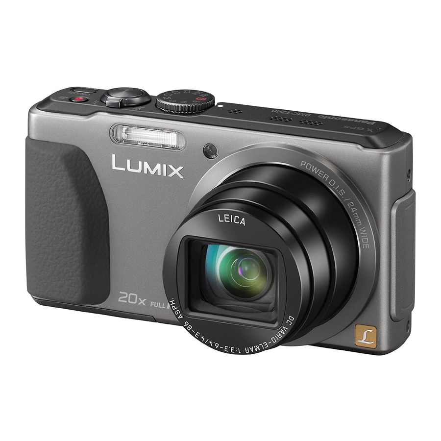
Table of Contents
Advertisement
Quick Links
DMC-TZ37EC
Model No.
DMC-TZ40EB
DMC-TZ40EE
DMC-TZ40EF
DMC-TZ40EG
DMC-TZ40EP
DMC-TZ40EA
DMC-TZ40GA
DMC-TZ40GC
DMC-TZ40GN
DMC-TZ41EG
DMC-ZS27PC
DMC-ZS30P
DMC-ZS30PC
DMC-ZS30PU
DMC-ZS30GK
DMC-ZS30GH
DMC-ZS30GT
Colours
(S)....................Silver Type (only DMC-TZ40EB/EE/EF/
EG/EP, TZ41, ZS30P/PC/GK)
(K)....................Black Type
(W)....................White Type (except DMC-TZ40EA,
TZ37EB/EC, ZS30PC/PU, ZS27P/PC)
(R)....................Red Type (except DMC-TZ37EB/EC,
ZS30P/PC/PU/GH, ZS27P/PC)
© Panasonic Corporation 2013.
Unauthorized copying and distribution is a violation
of law.
ORDER NO.DSC1303007CE
B26
Digital Camera
Advertisement
Table of Contents

Summarization of Contents
Safety Precautions
General Guidelines
General safety guidelines for servicing electrical equipment.
Leakage Current Cold Check
Procedure for checking cold leakage current.
Leakage Current Hot Check
Procedure for checking hot leakage current.
Warning
Prevention of Electrostatic Discharge (ESD)
Techniques to prevent damage to sensitive electronic components from static electricity.
How to Recycle the Lithium Ion Battery
Information on recycling lithium-ion batteries in the U.S.
How to Replace the Lithium Battery
Procedure for safely replacing the lithium battery in the device.
Service Navigation
3.1 Introduction
Overview of the service manual's structure and purpose.
3.2 Service Navigation
Details on lens block components and the VENUS ENGINE IC.
3.3 Service Notes
Important notes on Wi-Fi function and privacy protection.
3.4 General Description About Lead Free Solder (PbF)
Description and service cautions for lead-free solder (PbF).
3.5 How to Define the Model Suffix (NTSC or PAL model)
Methods to identify model suffixes (NTSC/PAL) based on nameplate.
3.5.2 INITIAL SETTINGS
Step-by-step guide for performing initial settings after PCB replacement.
Service Mode
6.1 Error Code Memory Function
How to display and interpret error codes stored in memory.
Troubleshooting Guide
7.1 Failure Diagnosis of GPS
Methods to diagnose and check GPS function failures.
7.2 Failure Diagnosis of Wi-Fi
Procedure for diagnosing issues with the Wi-Fi module.
7.3 Failure Diagnosis of NFC
Flowchart for checking and diagnosing NFC function failures.
Service Fixture & Tools
8.1 Service Fixture and Tools
List and description of special tools required for service.
8.2 When Replacing the Main P.C.B.
Important notes regarding adjustment after replacing the Main P.C.B.
8.3 Service Position
Information on service positions and required extension cable connections.
Disassembly and Assembly Instructions
9.1 Disassembly Flow Chart
Overall flowchart for disassembling the camera unit.
9.2 P.C.B. Location
Diagram showing the location of various P.C.B. units.
9.3 Disassembly Procedure
Detailed step-by-step instructions for disassembling camera components.
9.4 Lens Disassembly Procedure
Step-by-step guide for disassembling the camera lens unit.
9.5 Assembly Procedure for Lens (Revised Version)
Revised step-by-step instructions for reassembling the camera lens unit.
9.6 Removal of the MOS Unit
Procedure for removing the MOS image sensor unit.
Measurements and Adjustments
10.1 Introduction
Overview of necessary adjustments after component replacement.
10.2 Before Disassembling the unit
Initial setting release and data backup procedures before disassembly.
10.3 Details of Electrical Adjustment
Detailed procedures and specifications for electrical adjustments.
10.4 After Adjustment
Initial setting procedures required after completing electrical adjustments.
Maintenance
11.1 Cleaning Lens, Viewfinder and LCD Panel
Instructions for cleaning the lens, viewfinder, and LCD panel.
Block Diagram
12.1 Overall Block Diagram
High-level block diagram of the camera's internal components and connections.
12.2 System Control Block Diagram
Detailed block diagram of the camera's system control.
12.3 Audio/Video Process/ HDMI Block Diagram
Block diagram illustrating audio/video processing and HDMI interface.
12.4 Lens Drive Block Diagram
Block diagram showing the lens drive mechanisms and controls.
12.5 Power Block Diagram
Block diagram illustrating the camera's power supply system.
Wiring Connection Diagram
13.1 Interconnection Schematic Diagram
Schematic showing interconnection of all P.C.B. units and components.


Need help?
Do you have a question about the Lumix DMC-TZ41EG and is the answer not in the manual?
Questions and answers