Sony Handycam DCR-PC104E Service Manual
Digital video camera recorder
Hide thumbs
Also See for Handycam DCR-PC104E:
- Operating instructions manual (316 pages) ,
- Service manual (325 pages)
Table of Contents
Advertisement
Quick Links
SERVICE MANUAL
Ver 1.0 2003. 04
Revision History
Revision History
Link
Link
SPECIFICATIONS
SPECIFICATIONS
SERVICE NOTE
SERVICE NOTE
DISASSEMBLY
DISASSEMBLY
• For INSTRUCTION MANUAL, refer to SERVICE MANUAL, LEVEL 1 (987625841.pdf).
• Reference No. search on printed wiring boards is available.
On the VC-319 board
This service manual provides the information that is premised the circuit board replacement service and not intended repair
inside the VC-319 board.
Therefore, schematic diagram, printed wiring board, waveforms, mounted parts location and electrical parts list of the VC-319
board are not shown.
The following pages are not shown.
Schematic diagram ............................. Pages 4-25 to 4-60
Printed wiring board ............................ Pages 4-77 to 4-80
Waveforms ........................................... Pages 4-85 to 4-86
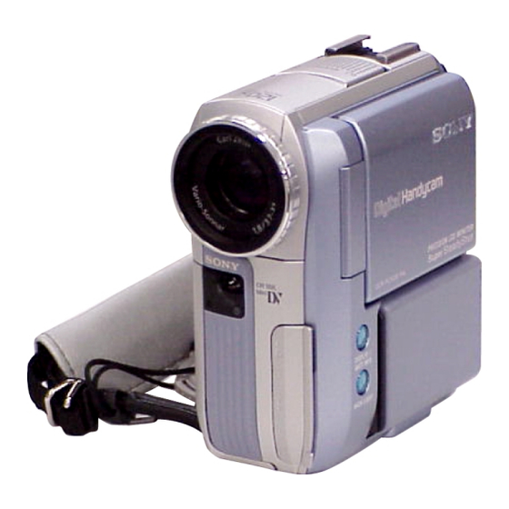
DCR-PC103E/PC104E/
Photo : DCR-PC103E
BLOCK DIAGRAMS
BLOCK DIAGRAMS
FRAME SCHEMATIC DIAGRAMS
FRAME SCHEMATIC DIAGRAMS
SCHEMATIC DIAGRAMS
SCHEMATIC DIAGRAMS
Mounted parts location ............................. Page 4-89 to 4-90
Electrical parts list ................................... Pages 5-15 to 5-23
DIGITAL VIDEO CAMERA RECORDER
PC105/PC105E
RMT-830/RMT-831
LEVEL
US Model
Canadian Model
Korea Model
AEP Model
UK Model
East European Model
DCR-PC103E/PC105E
E Model
Hong Kong Model
DCR-PC104E/PC105/PC105E
Chinese Model
DCR-PC104E/PC105E
Australian Model
Tourist Model
DCR-PC105/PC105E
Z MECHANISM
PRINTED WIRING BOARDS
PRINTED WIRING BOARDS
REPAIR PARTS LIST
REPAIR PARTS LIST
2
DCR-PC105
DCR-PC105E
Advertisement
Table of Contents

Related Manuals for Sony Handycam DCR-PC104E


Summarization of Contents
Specifications
Technical Specifications
Detailed data on video, audio, power, physical dimensions, and operational parameters.
Supplied Accessories
Lists all items included with the camcorder as standard accessories.
Service Note
Safety Check-out Procedures
Steps to perform after repair to ensure the unit is safe for customer use.
Flash Capacitor Discharge Procedure
Critical safety procedure to discharge high-voltage flash capacitors before servicing.
Self-Diagnosis Functionality
Explanation of the unit's diagnostic codes, displays, and troubleshooting tables.
Disassembly Procedures
Disassembly Flowchart
Visual guide illustrating the sequence of disassembly steps for various parts.
Component Removal Steps
Detailed instructions for removing specific assemblies and parts, starting with LCD Cabinet.
Block Diagrams
Overall System Diagrams
Comprehensive diagrams showing the camcorder's overall system architecture and signal paths.
Power Distribution Diagrams
Diagrams illustrating the camcorder's power distribution and supply circuits.
Schematic Diagrams
Schematic Diagram Conventions
Common notes and conventions applicable to all schematic diagrams within the manual.
Board-Specific Schematics
Detailed electrical schematics for individual circuit boards like CD-444, VF-156, PD-193, etc.
Printed Wiring Boards
Printed Wiring Board Layouts
Visual representations of component placement and routing on various circuit boards.
Repair Parts List
Exploded Views of Components
Illustrated diagrams showing the physical breakdown of the camcorder for part identification.
Electrical Parts Listing
Detailed listing of electrical components with part numbers and specifications.
Need help?
Do you have a question about the Handycam DCR-PC104E and is the answer not in the manual?
Questions and answers