Advertisement
Table of Contents
- 1 Table of Contents
- 2 Room Air Conditioner
- 3 Product Specifications
- 4 Pressure Graph
- 5 Operating Instructions
- 6 Replace Pcb Model Option
- 7 Disassembly and Reassembly
- 8 Refrigerating Cycle Diagram
- 9 Set up the Model Option
- 10 Option Items
- 11 Troubleshooting
- 12 Fault Diagnosis of Major Parts
- 13 Exploded Views and Parts List
- 14 PCB Diagram
- 15 Wiring Diagram
- Download this manual
SERVICE
AIR CONDITIONER
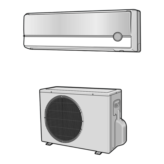
ROOM AIR CONDITIONER
INDOOR UNIT
SH09BPD
SH12BPD
Manual
CONTENTS
OUTDOOR UNIT
SH09BPDX
SH12BPDX
Advertisement
Table of Contents

Related Manuals for Samsung SH12BPDX


Summary of Contents for Samsung SH12BPDX
-
Page 1: Table Of Contents
ROOM AIR CONDITIONER INDOOR UNIT OUTDOOR UNIT SH09BPD SH09BPDX SH12BPD SH12BPDX Manual SERVICE AIR CONDITIONER CONTENTS 1. Product Specifications 2. Operating Instructions 3. Disassembly and Reassembly 4. Refrigerating Cycle Diagram 5. Set Up the Model Option 6. Troubleshooting 7. Exploded Views and Parts List 8. -
Page 2: Product Specifications
1. Product Specifications 1-1 Table Model SH09BPD SH12BPD SH09BPDX SH12BPDX Item Power Source ø-V-Hz 1-220/240-50 1-220/240-50 2,800(1,500~3,400) 3,500(1,500~4,000) Capacity BTU/h 9,500(5,100~11,600) 11,900(5,100~13,600) Energy Efficiency Ratio BTU/wh 11.8(10.0~13.8) 10.9(10.2~13.8) Cooling Air Flow /min Moisture Removal Noise Level Indoor Perfor- Noise Level... -
Page 3: Pressure Graph
1-2 Pressure Graph SH09BPD 32.4 30.6 28.8 27.0 24.0 21.5 Outdoor inlet air DB temp.( C) SH12BPD 32.4 30.6 28.8 27.0 24.0 21.5 Outdoor inlet air DB temp.( C) Samsung Electronics... -
Page 4: Operating Instructions
The sleep timer can be used when you are cooling or heating your room to switch the air conditioner off automatically after a period of 6 hours. Anion button. Press the button to generate ion from the air conditioner. Samsung Electronics... - Page 5 After setting On Timer or Off Timer, press the button to set it completely. And press the button again to cancel On Timer or Off Timer set. Digital On/Off button. If you want to turn off the display during operation press the button. Samsung Electronics...
- Page 6 Room Temperature Operating Mode Temperature Setting heat exchanger temperature and accumulating time of Less than 21˚C Heat 22˚C approx. compressor's operation. 21˚C or above Cool 24˚C approx. Deice ends by sensing of the processing time by deice condition. Samsung Electronics...
- Page 7 The air conditioner can generate anion with an ionizer in the indoor unit. 13. BUZZER SOUND : Whenever the On/Off button is pressed or whenever change occurs to the condition which is set up or select, the compulsory operation mode, buzzer is sounded "beep". Samsung Electronics...
-
Page 8: Replace Pcb Model Option
2-2 Replace PCB Model option 2-2-1 Replace PCB model option Remove power cord Replace the PCB module Check the connection and plug in Replace another PCB Does all display lamp blink? Refer to set up the Model option(15~17page) Samsung Electronics... -
Page 9: Disassembly And Reassembly
6) Loosen one of the right screw and detach the Terminal Cover. 7) Detach the thermistor from the Front Grille. 8) Loosen 5 fixing screws of Front Grille. 9) Pull the lower left and right of discharge softly for the outside cover to be pulled out. Samsung Electronics... - Page 10 Power Cord) (Main PCB) 2) Detach the outdoor unit connection wire from the Terminal Block. 3) If pulling the main PCB up, it will be taken out. 1) Pull Tray Drain out from the Back Body. Tray Drain Samsung Electronics...
- Page 11 1) Loosen 2 fixing screws and separate the Fan Motor Motor Holder. & Cross Fan 2) Loosen 1 fixing screw of Fan Motor. (with a M3 wrench) 3) Detach the Fan Motor from the Fan. 4) Detach the Fan from the left Holder Bearing. Samsung Electronics...
- Page 12 3) Loosen 5 fixing screws and detach the Cabinet-Upper. 4) Loosen 5 fixing screws from the Ass'y-Control Out. 5) Detach the Terminal-Housing from the Ass'y-Control Out. 6) Detach the Ass'y-Control Out from the outdoor unit. 7) Loosen 7 fixing screws and detach the Cabinet-Side. Samsung Electronics...
- Page 13 3) Detach the Fan. 4) Loosen 4 fixing screws to detach the Motor. Heat Exchanger 1) Loosen 3 fixing screws of Ass'y-Frame and Partition. 2) Disassemble the inlet and outlet pipe by welding. 3) Detach the Heat Exchanger. Samsung Electronics...
- Page 14 Connection Terminal. 2) Disassemble the inlet and outlet pipe of Compressor by welding. 3) Disassemble the inlet and outlet pipe of Condenser by welding 4) Loosen the 3 bolts of the lower part. 5) Detach the Compressor. Samsung Electronics...
-
Page 15: Refrigerating Cycle Diagram
4. Refrigerating Cycle Diagram Outdoor Unit Indoor Unit Capillary tube 2-Way valve Liquid side Heat Heat Exchanger Exchanger (Evaporator) (Evaporator) Gas side 3-Way valve 4-Way valve Cooling Heating Compressor Gas leak check point Samsung Electronics... -
Page 16: Set Up The Model Option
. . . repeatedly. Push the button to set the display panel to Setting is not required if you must Every time you push the button, the display panel reads a value which has a default..repeatedly. Samsung Electronics... - Page 17 If all lamps of indoor unit are flickering, Plug out, plug in again and press ON/OFF key to retry. If the unit is not working properly or all lamps are continuously flickering after setting the option code, see if the correct option code is set up for its model. Samsung Electronics...
-
Page 18: Option Items
Set up the Model Option OPTION ITEMS REMOCON SEG1 SEG2 SEG3 SEG4 SEG5 SEG6 SEG7 SEG8 SEG9 SEG10 SEG11 SEG12 MODEL SH09BPD SH12BPD Samsung Electronics... -
Page 19: Troubleshooting
The immediate operation starts Auto restart function is the convenient function where the operation state is without control of remote controller memorized in the Memory IC during the blackout and the operation restarts when when plugged the power comes back. Samsung Electronics... - Page 20 Temp-Sensor OLP temp-sensor Temp-Sensor Outdoor control PCB error Communication error between 2 micom on the outdoor PCB current sensor error heatsink temp-sensor error Voltage sensor error PCB, Outlet voltage Error display : and 2-digit-number are displayed alternately Samsung Electronics...
- Page 21 Trouble of deice temp-sensor (open / short) Deice sensor temperature is too low under minus ambient temperature operation (sensor normal) Trouble of heatsink temp-sensor circuit (open / short) Trouble of DC link voltage circuit Trouble of OLP temp-sensor (open / short) Samsung Electronics...
- Page 22 Check the outdoor unit In case of Error Code : Er/37(I), Er/38(K) In case of Error Code : Er/11(J), Er/12(M), Er/13(M), Er/14(L), Check the outdoor unit and In case of Error Code : Er/15(N), Er/18(O) outdoor unit installation Samsung Electronics...
- Page 23 Take out the thermistor connected to the connector (CN41,CN42) of control board of indoor unit and measure the resistance between two wires and if it is same as follows: it is normal but if not, replace it. Ambient temperature 15°C 20°C 25°C 30°C 35°C 40°C (°C) Resistance of 14.68 12.09 8.31 6.94 5.83 thermistor [KΩ] Samsung Electronics...
- Page 24 (PIN#3,4 of CN51 - discharge temperature sensor), (PIN#1,2 of CN52-OLP Temperature sensor) Measure the resistance between two wires and if it is same as follows, it is normal but if not, replace. Ambient temperature 0°C 10°C 20°C 30°C 40°C 50°C (°C) Resistance of thermistor [KΩ] Samsung Electronics...
- Page 25 • R461 4.7K 6-3-10 (K) Check of Current sensor, Voltage sensor and Communication between 2 micom on the board. √ These errors are from component trouble on the outdoor control board. → Replace the outdoor control board √ Samsung Electronics...
- Page 26 • If the comp is locked. → Replace the comp. • • If the comp is operating without the revolution of fan motor → Take out the protection cover. • → Check the fan motor connector and replace the fan motor. • Samsung Electronics...
- Page 27 • Gas pressure balance is not good at stop condition. → Check service valve open. √ • → Check EEV motor attachement and connector. √ • √ • Compressor is locked or have some mechanical damage. → Replace the compressor. √ • Samsung Electronics...
-
Page 28: Fault Diagnosis Of Major Parts
Approx. 290Ω at ambient temperature (20°C ~30°C) ∞, OΩ … open or short Abnormal Measure resistance between red wire and each terminal. Stepping Motor (FRONT GRILLE motor) Normal Approx. 110Ω at ambient temperature (20°C ~30°C) ∞, OΩ … open or short Abnormal Samsung Electronics... -
Page 29: Exploded Views And Parts List
7. Exploded Views and Parts List 7-1 Indoor Unit 12-4 12-6 12-1 12-3 7-10 12-2 12-5 1-1-2 1-1-3 1-1-1 1-1-4 1-1-5 1-1-6 1-1-7 You can search for the updated part code number through the ITSELF. URL : http://itself.sec.samsung.co.kr Samsung Electronics... - Page 30 Exploded Views and Parts List Parts List Q'TY Code No. Description Specification Remark SH09BPD SH12BPD DB92-00383A ASS'Y PANEL FRONT TOTAL ASS'Y DB92-00392A ASS'Y PANEL FRONT SUB ASS'Y 1-1-1 DB92-00346A ASS'Y PANEL FRONT ASS'Y 1-1-2 DB31-00166A MOTOR STEPPING 1-1-3 DB39-00780A CONNECT WIRE-STEP MOTOR...
- Page 31 7-2 Outdoor Unit 21-1 Samsung Electronics...
- Page 32 EPDM DB63-10034A COVER-TERMINAL NORYL DB32-10043B THERMISTOR-OLP 204CT / 103AT DB60-30018A NUT-FLANGE M5, SM20C DB99-00026B ASS'Y-4WAY VALVE 25kg/cm2G DB99-00041A ASS'Y-CHECK VALVE ASS'Y DB96-00279A ASS'Y-CONDENSER ASS'Y 21-1 DB32-10040A THERMISTOR-OUT 204CT / 103AT DB64-00186A CABI-SIDE SECC-P DB67-90024A HANDLE-CABI, LF DB63-00070A COVER-VALVE Samsung Electronics...
- Page 33 7-3 Ass'y Control In (Indoor Unit) SH09BPD / SH12BPD : DB93-02583A Samsung Electronics...
- Page 34 DB39-00820A C/W ION-PCB ASS'Y DB61-01110A HOLDER-DISPLAY DB64-00763A HALF MIRROR 95,T1.5 2301-001339 FAN CAPACITOR 1.2 µF/450V DB72-00126N SEAL T3, FOAM-PE,GRAY DB32-00084B THERMISTOR OUT,ø6,220 DB32-00054B THERMISTOR IN,ø5,200 DB39-00183A C/W FAN_CAP UL1015 AWG #22 DB93-01549C POWER CORD 6001-001054 SCREW-MACHINE TH M4xL10 Samsung Electronics...
- Page 35 7-4 Ass'y Control Out (Outdoor Unit) SH09BPDX / SH12BPDX : DB93-02582A Samsung Electronics...
- Page 36 M4x25 WSP PH+ RUBBER CLAMP DB61-40249A HOLDER WIRE RESIN-ABS 6006-001051 SCREW-MACHINE M4x16 WSP PH+ DB61-00745A COVER CASE CONTROL UP RESIN-ABS FOAMLEX 165x30xT2 HEATPROOF MICA 17.4x22.3xT0.5 WIRE SADDLE ST750294-3/MG620023 31x25,6NB DB39-00609C CONNECTOR WIRE AC UL1015 AWG#20 DB93-00963A RUN CAPACITOR 1.7µF/450V Samsung Electronics...
-
Page 37: Pcb Diagram
8. PCB Diagram 8-1 ASS'Y PCB Indoor Unit : DB93-02584A Samsung Electronics... - Page 38 PCB Diagram BOTTOM Samsung Electronics...
- Page 39 R606 R-CHIP 560ohm,5%,1/10W,TP,1068 R706 R-CHIP 100Kohm,5%,1/8W,TP,2012 R202,R203,R304,R205 R-CHIP 100Kohm,5%,1/4W,TP,3216 R707 R-CHIP 1Kohm,5%,1/8W,TP,2012 R102,R103,R104 R-CHIP 220Kohm,5%,1/4W,TP,3216 R106,R407 R-CHIP 220ohm,5%,1/8W,TP,2012 R101 R-CHIP 4.7Kohm,5%,1/8W,TP,2012 R105 R-CHIP 470ohm,5%,1/8W,TP,2012 R402,R501,R502,R503 R-CHIP 6.8Kohm,1%,1/10W,TP,1068 R303 R-CHIP 8.2Kohm,1%,1/10W,TP,1068 C104 C-CERAMIC,DISC 2.2NF,20%,400V,Y5U,BK,12.5x6mm,10 C103,C107,C110,C112,C201 C-CER,CHIP 100nF,+80-20%,50V,Y5V,TP,2012 C202,C500,C501,C502,C503 C901 Samsung Electronics...
- Page 40 CN51 CONNECTOR-HEADER BOX,14P,1R,2mm,STRAIGHT,SN CN53 CONNECTOR-HEADER BOX,3P,1R,2mm,STRAIGHT,SN CN61 CONNECTOR-HEADER BOX,5P,1R,2mm,STRAIGHT,SN CN41 CONNECTOR-HEADER BOX,4P,1R,2mm,STRAIGHT,SN,WHT CN81 CONNECTOR-HEADER BOX,3P,1R,2mm,STRAIGHT,SN,BLU IC02 KA78L05AZTA(0.1A,Positive,Vol,Reg) IC04 IC MICOM MB89538APF-101,MB89538APF-101,64P,+5V,10M ST11 TRANS SWITCHING DC12V,-,-,-,-,-,-,12V,0.01A,-,E119 POSISTOR DSA-332MA,2pF MAX,100Mohm,ASM-3 LEAD-WIRE UL1015 AWG#20 GRN/YEL FT72 LS403110 C001 SC102M Y-CAP 7.5mm Samsung Electronics...
- Page 41 8-2 ASS'Y PCB Outdoor Unit : DB93-02581A Samsung Electronics...
- Page 42 R406,R407 C202,C472,C501,C502,C503 C-CERAMIC CHIP;CL21F104ZANC,100nF,+80-20%,50V,Y5V,TP,2012 C504,C505,C706,C711,C719 C721,C722,C903 C407,C707 C-CERAMIC CHIP;CL21F102ZANC,1nF,10%,50V,X7R,TP,2012,- C701 C-CERAMIC CHIP;CL21B223KBNC,22nF,10%,50V,X7R,TP,2012 C204,C305,C306,C509,C510 C-CERAMIC CHIP;CL21F103ZANC,10nF,+80-20%,50V,Y5V,TP,2012 C513,C723 C405 C-CERAMIC CHIP;CL21B471KBNC,470pF,5%,50V,UJ,TP,2012,- SUB01 S3C848A S3C848A MAIN MICOM TMS320LF2406A TMS320LF2406A C301 C-FILM MPP;PC2J103K,10nF,10%,630V,TP,16x11x7.5mm C123 C-AL RADIAL;10uF,20%,450V,RG,12.5x20mm RY502,RY503 RELAY-MINIATURE F3AA012E RY01 RELAY-POWER 12VDC,UKH-125 Samsung Electronics...
- Page 43 READIAL;RZ,35V,47uF,6.3x11,TP C107,C109,C112,C114,C115 C-AL EC-DIP;WD,25V,220uF,8x11.5,TP C116,C464,C466,C471 BD01 BRIGDE-DIODE GS1B2560 CN04 CONNECTOR-HEADER YAW396-03AV/WHT CN51 CONNECTOR-HEADER SMAW250A-04/RED CN52 CONNECTOR-HEADER SMAW250A-04/WHT CN53 CONNECTOR-HEADER SMAW250-06/WHT CN54 CONNECTOR-HEADER YAW396-05AV/WHT FUSE FUSE-CARTRIDGE 250V,20A,65TL,SLOW-BLOW,CERAMIC,6.35x31. IC14 IC-REG KA7812,1A,TO-220,3P TR-IGBT FSAM155M60A C415,C416,C417 C-CERAMIC CHIP;CL21F104ZANC,100nF,+80,-20%,50V,Y5V,TP,2012 C440,C462,C702,C716 C-CERAMIC CHIP;CL21F105ZANC,1uF 2012 Samsung Electronics...
- Page 44 KA431DTF KA431DTF(3-Terminal,Adjustable,Reg) D103,D106 CHIP,ES1D,DO-214AC,200V IC15,IC56,IC57 TLP181(GRH-TLP),SOP,TP,11-4C Q202,Q301,Q302,Q502,Q503 TR-DIGITAL KRC102S,NPN,200mW,10K-10K.SOT Q702 Q703,Q704,Q901 R408,R409,R410 R-CHIP MCR10EZH;J331,33ohm,1/8W,2012 R457 R-CHIP MCR10EZH;J1021Kohm,5%,1/8W,DA,TP,2012 R459 R-CHIP 30Kohm,1%,1/10W,DA,TP,2012 R907 R-CEMENT 0.020ohm 5% MPR 7W C436 C-FILM MPP,RADIAL,PC2J104K 100nF 630V 1.5U R461 R-CHIP MCR10EZH;J472,4.7Kohm,5%,1/8W,DA,TP,2012 R709 R-CHIP MCR10EZH;J10R0,10ohm,5%,1/8W,DA,TP,2012 Samsung Electronics...
- Page 45 PCB Diagram BOTTOM Samsung Electronics...
- Page 46 C703,C704 CHIP;CL21C220JBNC 220pF D104,D105,D301 CHIP;ES1D,DO-214AC,200V IC21,IC31,IC32 PHOTO-COUPLER TLP181(GRH-TLP),SOP,TP,11-4C Q201,Q802 TR-DIGITAL KRC102S,NPN,200mW,10K-10K,SOT IC83 IC-LOGIC LM324D Q003 IC-TR BC847B,NPN,SOT-23 R103 R-CHIP 620ohm,5%,1/10W,DA,TP,2012 R104 R-CHIP MCR10EZH;J222,2.2Kohm,1/8W,5%,2012 R106 R-CHIP 3.3Kohm,1/8W,1%,2012 R478 R-CHIP MCR10EZH;J103,10Kohm,5%,1/8W,DA,TP,2012 R480 R-CHIP 390ohm,1%,1/10W,DA,TP,2012 R910 R-CHIP 3.3Kohm,1%,1/8W,DA,TP,2012 C111,C113,C712,C715,C718 C-CERAMIC CHIP;CL21F105ZANC,1uF,2012 Samsung Electronics...
- Page 47 C467 C-CERAMIC CHIP;CL21B333KBNC 33nF 50V,2012 D201 DIODE-RECTIFIER US1G,DO-214AC,400V IC42 IC-Compare KA239D,14-SOP,TP R110,R111 R-CHIP MCR100EZH;J184,180Kohm,5%,1W,6432 R412,R427,R428,R434,R441 R-CHIP MCR100EZH;F3003,300Kohm,1%,1W,6432 R803 R-CHIP 2.2Kohm,1%,1W,6432 R805 R-CHIP 3.3Kohm,1%,1/8W,2012 R901 R-CHIP RC2012J681CS;680ohm,5%,2012 ZD81,ZD82 DIODE-ZENER BZX84C3V6SOT-23T,3.6V,350M R112,R113,R114 R-CHIP MCR18EZH;F4703,470Kohm,1/4W,1%,3216 R002,R003 MCR50EZH F4703,470Kohm,1/2W,40,5025 C104,C105,C304 C-CERAMIC DISC;RADIAL,SCE,222M,10FF7 Samsung Electronics...
- Page 48 8-3 ASS'Y DISPLAY PCB(9K / 12K) : DB93-01368G Parts List Description Specification Q'TY Remark ASS'Y LED MODULE PCB-DISPLAY FR-1 T1.6 TACT SWITCH KPT-1105A TSTA-2 RESISTOR 200ohm, 2W RESISTOR 100ohm, 2W CONNECTOR WIRE Samsung Electronics...
- Page 49 8-4 ASS'Y MODULE PCB(9K / 12K) : DB93-01369A Parts List Description Specification Q'TY Remark PCB-DISPLAY FR-1 T1.6 CONNECTOR SMAW200-03P(WHT) C-CERAMIC CA OA 50V 102K DIODE SWITCHING 1N4148 C-CERAMIC CA OA 50V 104Z MODULE REMOCON FRP4021-H7(7mm) Samsung Electronics...
-
Page 50: Wiring Diagram
9. Wiring Diagram 9-1 Indoor Unit(9K / 12K) Code No : DB98-16258A This Document can not be used without Samsung's authorization. Samsung Electronics... - Page 51 9-2 Outdoor Unit(9K / 12K) Code No : DB98-16257A This Document can not be used without Samsung's authorization. Samsung Electronics...
- Page 52 MEMO Samsung Electronics...
- Page 53 MEMO Samsung Electronics...
- Page 54 MEMO Samsung Electronics...
- Page 55 MEMO Samsung Electronics...
- Page 56 ELECTRONICS © Samsung Electronics Co., Ltd. Feb. 2004. This Service Manual is a property of Samsung Electronics Co., Ltd. Any unauthorized use of Manual can be punished under applicable Printed in Korea. International and/or domestic law. Code No. DB98-00000A(1)
Need help?
Do you have a question about the SH12BPDX and is the answer not in the manual?
Questions and answers