
Related Manuals for Toshiba RAS-24SKHP-ES


Summarization of Contents
2. CONSTRUCTION VIEWS
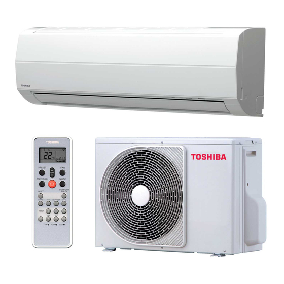
2-1. Indoor Unit
Diagrams and dimensions of the indoor unit.
2-2. Outdoor Unit
Diagrams and dimensions of the outdoor unit.
3. WIRING DIAGRAM
3-1. RAS-18SKP-ES / RAS-18SA-ES, RAS-24SKP-ES / RAS-24SA-ES
Wiring diagram for specific models.
3-2. RAS-18SKHP-ES / RAS-18S2AH-ES, RAS-24SKHP-ES / RAS-24S2AH-ES
Wiring diagram for other specific models.
4. SPECIFICATION OF ELECTRICAL PARTS
4-1. Indoor Unit (RAS-18SKP-ES, RAS-24SKP-ES)
List of indoor unit electrical parts and specs.
4-2. Outdoor Unit (RAS-18SA-ES)
List of outdoor unit electrical parts and specs.
4-3. Outdoor Unit (RAS-24SA-ES)
List of outdoor unit electrical parts and specs.
4-4. Indoor Unit (RAS-18SKHP-ES, RAS-24SKHP-ES)
List of indoor unit electrical parts and specs.
4-5. Outdoor Unit (RAS-18S2AH-ES)
List of outdoor unit electrical parts and specs.
4-6. Outdoor Unit (RAS-24S2AH-ES)
List of outdoor unit electrical parts and specs.
5. REFRIGERATION CYCLE DIAGRAM
5-1. RAS-18SKP-ES / RAS-18SA-ES
Refrigeration cycle diagram for specific models.
5-2. RAS-24SKP-ES / RAS-24SA-ES
Refrigeration cycle diagram for specific models.
5-3. RAS-18SKHP-ES / RAS-18S2AH-ES
Refrigeration cycle diagram for specific models.
5-4. RAS-24SKHP-ES / RAS-24S2AH-ES
Refrigeration cycle diagram for specific models.
6. CONTROL BLOCK DIAGRAM
6-1 RAS-18SKP-ES / RAS-18S2A-ES, RAS-24SKP-ES / RAS-24S2A-ES
Control block diagram for specific models.
6-2 RAS-18SKHP-ES / RAS-18S2AH-ES, RAS-24SKHP-ES / RAS-24S2AH-ES
Control block diagram for other specific models.
7. OPERATION DESCRIPTION
7-1. Remote control
Details on the remote control functions and buttons.
7-2. Outline of Air Conditioner Control
Overview of indoor and outdoor unit control functions.
8. INSTALLATION PROCEDURE
8-1. Safety Cautions
Important safety precautions for installation.
8-2. Installation Diagram of Indoor and Outdoor Units
Visual guide for unit installation placement and components.
8-3. Installation
Details about installation process and parts.
3-3-3. Installation/Servicing Tools
Special tools required for R410A air conditioner installation.
8-4. Indoor Unit
Guidelines and procedures for indoor unit installation.
8-5. Outdoor Unit
Guidelines and procedures for outdoor unit installation.
8-6. Test Operation
Steps to perform system testing and initial setup.
9. TROUBLESHOOTING CHART
9-1. Troubleshooting Procedure
General procedure for troubleshooting operational issues.
9-2. Basic Check Items
Initial checks for common operational problems.
9-3. Primary Judgement
Initial diagnosis of faults based on symptoms and indicators.
9-4. Self-Diagnosis by Remote Controller (Check Code)
Using the remote control to diagnose faults via specific check codes.
9-5. How To Diagnose Faulty Parts
Flowcharts for diagnosing specific faulty components.
9-6. Troubleshooting for Indoor unit
Steps to troubleshoot issues specific to the indoor unit.
9-7. Troubleshooting for Wiring (Interconnect cable and Serial Signal Wire)
Troubleshooting wiring issues between indoor and outdoor units.
9-8. Troubleshooting for P.C. board
Diagnosing issues related to the Printed Circuit Board (P.C. board).
11. EXPLODED VIEWS AND PARTS LIST
11-1. Indoor Unit (E-Parts Assy)
Exploded view and parts list for the indoor unit assembly.
11-2. Indoor Unit
Exploded view and parts list for the indoor unit.
11-3. Outdoor Unit (RAS-18SA-ES, RAS-24SA-ES)
Exploded view and parts list for specific outdoor units.
11-4. Outdoor Unit (RAS-18S2AH-ES, RAS-24S2AH-ES)
Exploded view and parts list for specific outdoor units.
Need help?
Do you have a question about the RAS-24SKHP-ES and is the answer not in the manual?
Questions and answers