Advertisement
Service
Manual
2nd EDITION
• The model no.SR4320/N1B/N1G was added in this service manual.
SECTION
1. TECHNICAL SPECIFICATIONS ............................................................................ 1
2. WIRING DIAGRAM................................................................................................ 3
3. BLOCK DIAGRAM................................................................................................. 5
4. SCHEMATIC DIAGRAM ........................................................................................ 7
5. PARTS LOCATION .............................................................................................. 11
6. IC DATA................................................................................................................ 21
7. EXPLODED VIEW AND PARTS LIST ................................................................. 25
8. SERVICE PROCEDURE ..................................................................................... 29
9. ELECTRICAL PARTS LIST ................................................................................. 30
Please use this service manual with referring to the user guide ( D.F.U. ) without fail.
Printed on 100% Recycled Paper
Printed in Japan
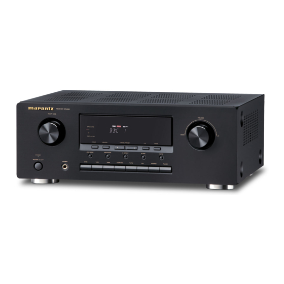
RECEIVER SR4320
MULTI - JOG
SPEAKERS
A
B
DISPLAY OFF
CLEAR
MEMORY
JOG MODE
SPEAKERS
STANDBY
POWER ON/OFF
PHONES
DVD
VCR
DSS
TABLE OF CONTENTS
SR4320
SR4320 /
DOWN
TUNING/PRESET
F/P
MODE
S-DIRECT
SLEEP
MUTE
CDR/MD
TAPE
CD
PHONO
TUNER
A1B/N1B/U1B
Receiver
VOLUME
UP
PAGE
Part no. 19AW855012
2nd Issue 2003.12
/N1G
ecm
Advertisement
Table of Contents

Related Manuals for Marantz SR4320/U1B


Summarization of Contents
Marantz Product Design Philosophy
Ordering Parts Information
Details on how to order genuine Marantz parts from various global locations.
Critical Service Safety Precautions
Shock and Fire Hazard Test Procedure
Mandatory safety checks, including resistance measurements, before returning the unit to customers to prevent hazards.
1. Technical Specifications
FM Tuner Section Specifications
Technical details for the FM tuner, including frequency range, sensitivity, and distortion.
AM Tuner Section Specifications
Technical details for the AM tuner, including frequency range, sensitivity, and distortion.
Audio Section Specifications
Technical details for the audio output, including rated power, THD, and input sensitivity.
General Specifications
Includes power supply, power consumption, dimensions, and weight of the unit.
Included Accessories List
List of items supplied with the product, such as remote control, antennas, and manuals.
5. Parts Location
Various PCB Parts Location
Diagrams showing component layout for Video, Power, H/P, Volume, and Power SW PCBs.
6. IC Data
Integrated Circuit Block Diagrams
Block diagrams for various integrated circuits (IC22, IC24, IC63, IC23) used in the unit.
IC71 NJM2279 Data
Pin assignment and block diagram details for the IC71 NJM2279.
IC91 TMP87PM78F Details
IC91 TMP87PM78F Pin Assignment
Detailed pin configuration and function for the IC91 TMP87PM78F microcontroller.
IC91 TMP87PM78F Block Diagram
Functional block diagram illustrating the internal structure of the IC91 TMP87PM78F.
8. Service Procedure
Tuner Alignment Instructions
Steps and required equipment for performing tuner alignment procedures.
Alignment Procedure Steps
Detailed steps for aligning modulation and frequency for AM and FM bands.
9. Electrical Parts List
Parts Code Definitions and Lists
Definitions for common parts codes, including resistors, capacitors, and abbreviations.
Safety and Fuse Information
Crucial safety notes on component replacement, fuses, and hazard warnings.
Need help?
Do you have a question about the SR4320/U1B and is the answer not in the manual?
Questions and answers